Nissan Versa (N17): C1708, C1709, C1710, C1711 Transmitter (no data)
DTC Logic
NOTE: The Signal Tech II Tool (J-50190) can be used to perform the following functions. Refer to the Signal Tech II User Guide for additional information.
- Activate and display TPMS transmitter IDs
- Display tire pressure reported by the TPMS transmitter
- Read TPMS DTCs
- Register TPMS transmitter IDs
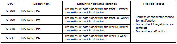
DTC DETECTION LOGIC
DTC CONFIRMATION PROCEDURE
1.PERFORM SELF DIAGNOSTIC RESULT
With CONSULT
- Drive for 3 minutes at a speed of 40 km/h (25 MPH) or more, then drive normally for 10 minutes.
- Stop the vehicle.
- Perform "SELF DIAGNOSTIC RESULT".
Is DTC "C1708", "C1709", "C1710" or "C1711" detected?
YES >> Proceed to WT "Diagnosis Procedure".
NO >> Inspection End.
Diagnosis Procedure
NOTE: The Signal Tech II Tool (J-50190) can be used to perform the following functions. Refer to the Signal Tech II User Guide for additional information.
- Activate and display TPMS transmitter IDs
- Display tire pressure reported by the TPMS transmitter
- Read TPMS DTCs
- Register TPMS transmitter IDs
Regarding Wiring Diagram information, refer to WT "Wiring Diagram".
1.CHECK DATA MONITOR
With CONSULT
- Drive for 3 minutes at a speed of 40 km/h (25 MPH) or more, then drive normally for 10 minutes.
- Stop the vehicle.
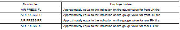
- On "DATA MONITOR" select "AIR PRESS FL", "AIR PRESS FR", "AIR PRESS RR" and "AIR PRESS RL".
- Within 5 minutes after vehicle is stopped, read the values displayed on CONSULT.
Are all tire pressures displayed 0 kPa (psi)?
YES >> GO TO 2.
NO >> GO TO 5.
2.CHECK REMOTE KEYLESS ENTRY RECEIVER POWER CIRCUIT
Check voltage between remote keyless entry receiver connector and ground.
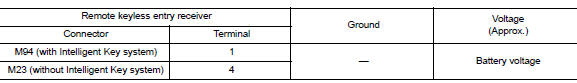
Is the inspection result normal?
YES >> GO TO 3.
NO >> Repair or replace harness or connectors.
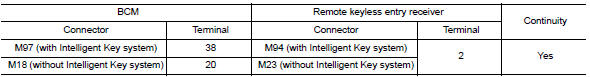
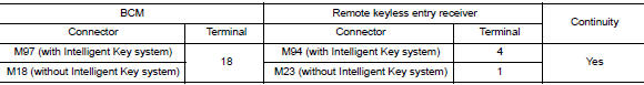
3.CHECK REMOTE KEYLESS ENTRY RECEIVER SIGNAL CIRCUIT
- Turn the ignition switch OFF.
- Disconnect BCM and remote keyless entry receiver connectors.
- Check continuity between BCM and remote keyless entry receiver
connectors.
4. Check continuity between BCM connector and
ground. 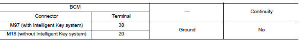
Is the inspection result normal?
YES >> GO TO 4.
NO >> Repair or replace the malfunctioning harness or connector.
4.CHECK REMOTE KEYLESS ENTRY RECEIVER GROUND CIRCUIT
Check continuity between BCM and remote keyless entry receiver connectors.
Is the inspection result normal?
YES >> GO TO 5.
NO >> Repair or replace the malfunctioning harness or connector.
5.TRANSMITTER ID REGISTRATION
Perform transmitter ID registration. Refer to WT "Work Procedure".
Is transmitter ID registration completed?
YES >> GO TO 6.
NO >> Replace applicable transmitter. Refer to WT "Removal and Installation".
6.CHECK TIRE PRESSURE SIGNAL
With CONSULT
- Drive for 3 minutes at a speed of 40 km/h (25 MPH) or more, then drive normally for 10 minutes.
- Stop the vehicle.
- On "DATA MONITOR" select "AIR PRESS FL", "AIR PRESS FR", "AIR PRESS RR" and "AIR PRESS RL".
- Within 5 minutes after vehicle stopped, check that the tire pressures
are within specification. Refer to WT-
"Tire Air Pressure".
Is the inspection result normal?
YES >> Inspection End.
NO >> Replace the BCM. Refer to BCS "Removal and Installation" or BCS "Removal and Installation".
 C1704, C1705, C1706, C1707 Low tire
pressure
C1704, C1705, C1706, C1707 Low tire
pressure
DTC Logic DTC DETECTION LOGIC DTC CONFIRMATION PROCEDURE 1.PERFORM SELF DIAGNOSTIC RESULT With CONSULT Turn the ignition sw ...

Other materials:
Security systems (if so equipped)
Your vehicle has one type of security systems:
NISSAN Vehicle Immobilizer System
NISSAN vehicle immobilizer system
The NISSAN Vehicle Immobilizer System will not
allow the engine to start without the use of a
registered key.
If the engine fails to start using a registered key
(for ex ...
Rear oil seal
REAR OIL SEAL : Removal and Installation
REMOVAL
Remove transaxle assembly.
Remove clutch cover and clutch disk (M/T models).
Remove flywheel (M/T models) or drive plate (A/T or CVT models).
Remove rear oil seal with a suitable tool.
CAUTION:
Be careful not to damage crankshaft an ...
Categories
- Manuals Home
- Nissan Versa Owners Manual
- Nissan Versa Service Manual
- Video Guides
- Questions & Answers
- External Resources
- Latest Updates
- Most Popular
- Sitemap
- Search the site
- Privacy Policy
- Contact Us

0.0056