Nissan Versa (N17): C1109 Power and ground system
DTC Logic
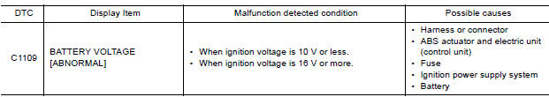
DTC DETECTION LOGIC
DTC CONFIRMATION PROCEDURE
1.CHECK SELF DIAGNOSTIC RESULT
With CONSULT.
- Turn the ignition switch ON.
- Perform self diagnostic result.
Is DTC C1109 detected?
YES >> Proceed to diagnosis procedure. Refer to BRC "Diagnosis Procedure".
NO >> Inspection End.
Diagnosis Procedure
Regarding Wiring Diagram information, refer to BRC "Wiring Diagram".
1.CONNECTOR INSPECTION
- Turn ignition switch OFF.
- Disconnect ABS actuator and electric unit (control unit) connectors.
- Check connectors and terminals for deformation, disconnection, looseness or damage.
Is the inspection result normal?
YES >> GO TO 2
NO >> Repair or replace as necessary.
2.CHECK ABS ACTUATOR AND ELECTRIC UNIT (CONTROL UNIT) IGNITION POWER SUPPLY CIRCUIT
Check voltage between ABS actuator and electric unit (control unit) connector
E33 terminal 28 and ground. 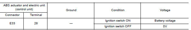
Is the inspection result normal?
YES >> GO TO 3
NO >> Repair or replace malfunctioning components.
3.CHECK ABS ACTUATOR AND ELECTRIC UNIT (CONTROL UNIT) GROUND CIRCUIT
- Turn ignition switch OFF.
- Check continuity between ABS actuator and electric unit (control unit)
connector E33 terminals 13, 38 and
ground.
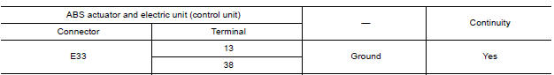
Is the inspection result normal?
YES >> Replace ABS actuator and electric unit (control unit). Refer to BRC "Removal and Installation".
NO >> Repair or replace malfunctioning components.
 C1105, C1106, C1107, C1108 Wheel sensor
C1110, C1153, C1170 ABS Actuator and
electric unit (control unit)
DTC Logic DTC DETECTION LOGIC DTC CONFIRMATION PROCEDURE 1.CHECK SELF-DIAGNOSIS RESULTS Check the self-diagnosis results. ...
Other materials:
A/T Fluid cooler
Cleaning
Whenever the A/T is repaired, overhauled, or replaced, the A/T fluid cooler
mounted in the radiator must be
inspected and cleaned.
Metal debris and friction material, if present, can become trapped in the A/T
fluid cooler. This debris can contaminate
the newly serviced A/T or, i ...
P0979 Shift solenoid C
DTC Logic
DTC DETECTION LOGIC
DTC
Trouble diagnosis name
DTC detection condition
Possible causes
P0979
Shift Solenoid C Control Circuit
Low
The following diagnosis conditions
are met, and the current
monitor reading of the TCM 2-4
brake solenoid valve is ...
Categories
- Manuals Home
- Nissan Versa Owners Manual
- Nissan Versa Service Manual
- Video Guides
- Questions & Answers
- External Resources
- Latest Updates
- Most Popular
- Sitemap
- Search the site
- Privacy Policy
- Contact Us

0.0059