Nissan Versa (N17): B2622 Inside antenna
DTC Logic
DTC DETECTION LOGIC 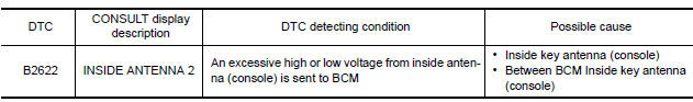
DTC CONFIRMATION PROCEDURE
1.PERFORM DTC CONFIRMATION PROCEDURE
- Select INTELLIGENT KEY of BCM using CONSULT.
- Select INSIDE ANT DIAGNOSIS in WORK SUPPORT mode.
- Perform inside key antenna (INSIDE ANT DIAGNOSIS) on WORK SUPPORT of INTELLIGENT KEY.
- Check BCM for DTC.
Is inside key antenna DTC detected?
YES >> Refer to DLK "Diagnosis Procedure".
NO >> Inside key antenna (console) is OK.
Diagnosis Procedure
Regarding Wiring Diagram information, refer to DLK "INTELLIGENT KEY SYSTEM : Wiring Diagram".
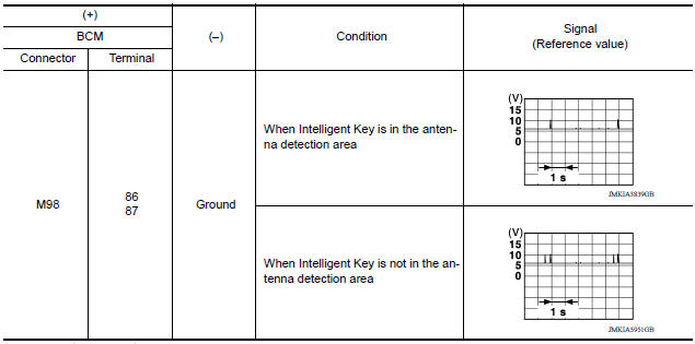
1.CHECK INSIDE KEY ANTENNA INPUT SIGNAL 1
- Turn ignition switch ON.
- Check signal between BCM harness connector and ground using
oscilloscope.
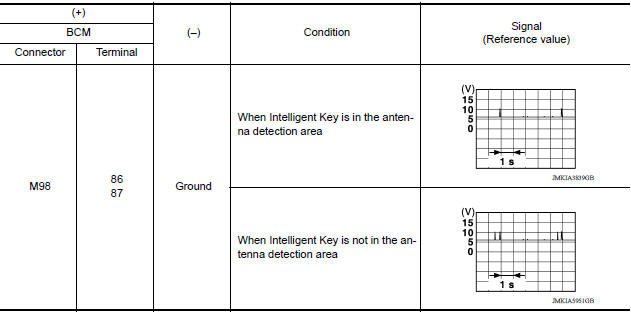
Is the inspection result normal?
YES >> Replace BCM. Refer to BCS "Removal and Installation".
NO >> GO TO 2.
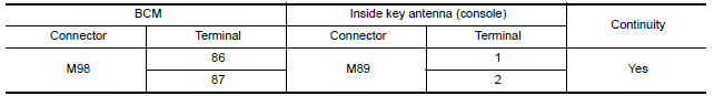
2.CHECK INSIDE KEY ANTENNA CIRCUIT
- Turn ignition switch OFF.
- Disconnect BCM connector and inside key antenna (console) connector.
- Check continuity between BCM harness connector and inside key antenna
(console) harness connector
- Check continuity between BCM harness connector and ground.
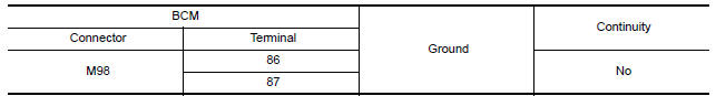
Is the inspection result normal?
YES >> GO TO 3.
NO >> Repair or replace harness.
3.CHECK INSIDE KEY ANTENNA INPUT SIGNAL 2
- Replace inside key antenna (console). (New antenna or other antenna)
- Connect BCM connector and inside key antenna (console) connector.
- Turn ignition switch ON.
- Check signal between BCM harness connector and ground using
oscilloscope.
Is the inspection result normal?
YES >> Replace inside key antenna (console).
NO >> Replace BCM. Refer to BCS "Removal and Installation".
 B2621 Inside antenna
Other materials:
Oil pump
Exploded View
1. Rear oil seal 2. Oring 3. Oil pan (upper)
4. Oil pump chain tensioner (for oil
pump drive chain)
5. Oil pump drive chain 6. Crankshaft key
7. Crankshaft sprocket 8. Oil pump sprocket 9. Oil pump
10. Oring 11. Oring 12. Oil pan drain plug
13. Drain plug washer 14. Oil pan ( ...
Calibration of G Sensor
Description
TCM stores calibration data (inherent characteristic value) of G sensor to
provide accurate control. Therefore,
it is required to perform calibration of G sensor after the following work is
performed.
Removal/installation or replacement of G sensor
Replacement of TCM
Work ...
Categories
- Manuals Home
- Nissan Versa Owners Manual
- Nissan Versa Service Manual
- Video Guides
- Questions & Answers
- External Resources
- Latest Updates
- Most Popular
- Sitemap
- Search the site
- Privacy Policy
- Contact Us

0.0059