Nissan Versa (N17): B2198 NATS antenna AMP
DTC Logic
DTC DETECTION LOGIC 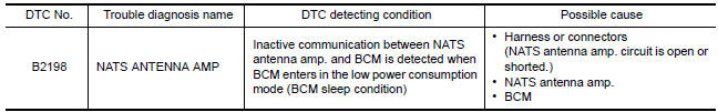
DTC CONFIRMATION PROCEDURE
1.PERFORM DTC CONFIRMATION PROCEDURE
1. Make the conditions that BCM enters in the low power consumption mode (BCM sleep condition).
Refer to BCS "BODY CONTROL SYSTEM : System Description".
2. Turn ignition switch ON.
3. Check DTC in Self Diagnostic Result mode of BCM using CONSULT.
Is DTC detected?
YES >> Go to SEC "Diagnosis Procedure".
NO >> Inspection End.
Diagnosis Procedure
Regarding Wiring Diagram information, refer to SEC "Wiring Diagram".
1.CHECK FUSE
1. Turn power switch OFF.
2. Check that the following fuse in IPDM E/R is not blown. 
Is the inspection result normal?
YES >> GO TO 2.
NO >> Replace the blown fuse after repairing the cause of blowing.
2.CHECK NATS ANTENNA AMP. POWER SUPPLY
1. Disconnect NATS antenna amp. connector.
2. Check voltage between NATS antenna amp. harness connector and ground. 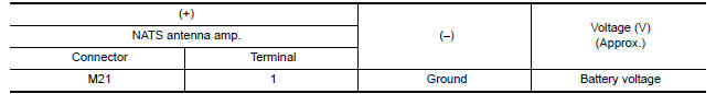
Is the inspection result normal?
YES >> GO TO 4.
NO >> GO TO 3.
3.CHECK NATS ANTENNA AMP. POWER SUPPLY CIRCUIT
1. Disconnect IPDM E/R connector.
2. Check continuity between IPDM E/R harness connector and NATS antenna amp.
connector.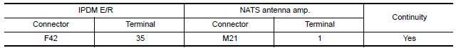
Is the inspection result normal?
YES >> Replace IPDM E/R. Refer to PCS "Removal and Installation".
NO >> Repair or replace harness.
4.CHECK NATS ANTENNA AMP. GROUND CIRCUIT
Check continuity between NATS antenna amp. harness connector and ground. 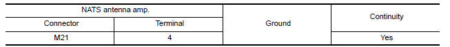
Is the inspection result normal?
YES >> GO TO 5.
NO >> Repair or replace harness.
5.CHECK NATS ANTENNA AMP. COMMUNICATION SIGNAL 1
Check voltage signal between NATS antenna amp. harness connector and ground
using an oscilloscope.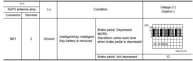
Is the inspection result normal?
YES >> GO TO 7.
NO >> GO TO 6.
6.CHECK NATS ANTENNA AMP. OUTPUT SIGNAL CIRCUIT 1
1. Disconnect BCM connector.
2. Check continuity between NATS antenna amp. harness connector and BCM
connector. 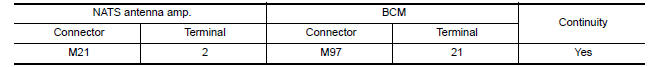
3. Check continuity between NATS antenna amp. harness connector and ground.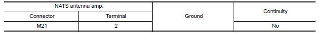
Is the inspection result normal?
YES >> GO TO 9.
NO >> Repair or replace harness.
7.CHECK NATS ANTENNA AMP. COMMUNICATION SIGNAL 2
Check voltage signal between NATS antenna amp. harness connector and ground
using an oscilloscope. 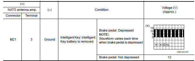
Is the inspection result normal?
YES >> Replace NATS antenna amp. Refer to SEC "Removal and Installation".
NO >> GO TO 8.
8.CHECK NATS ANTENNA AMP. OUTPUT SIGNAL CIRCUIT 2
1. Disconnect BCM connector.
2. Check continuity between NATS antenna amp. harness connector and BCM
connector.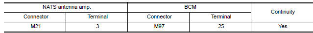
3. Check continuity between NATS antenna amp. harness connector and ground. 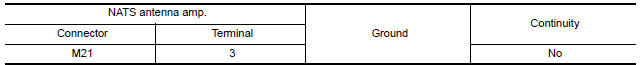
Is the inspection result normal?
YES >> GO TO 9.
NO >> Repair or replace harness.
9.REPLACE BCM
1. Replace BCM. Refer to BCS "Removal and Installation".
2. Perform initialization of BCM and registration of all Intelligent Keys using CONSULT.
>> Inspection End
 B2196 Dongle unit
Description BCM performs ID verification between BCM and dongle unit. When verification result is OK, BCM permits cranking. ...

Other materials:
Camshaft
Exploded View
1. Camshaft bracket (No. 2 to 5) 2. Camshaft bracket (No. 1) 3. Camshaft
sprocket (EXH)
4. Exhaust valve timing control solenoid
valve 5. Oring 6. Camshaft sprocket (INT)
7. Plug (EXH) 8. Washer (EXH) 9. Oil filter (for exhaust valve timing control
solenoid valve)
10. Cylinde ...
P0863 TCM Communication
DTC Logic
DTC DETECTION LOGIC
DTC
Trouble diagnosis name
DTC detection condition
Possible causes
P0863
TCM Communication Circui
An error is detected at the initial CAN diagnosis
of TCM.
TCM
DTC CONFIRMATION PROCEDURE
1.PREPARATION BEFORE WORK
If anothe ...
Categories
- Manuals Home
- Nissan Versa Owners Manual
- Nissan Versa Service Manual
- Video Guides
- Questions & Answers
- External Resources
- Latest Updates
- Most Popular
- Sitemap
- Search the site
- Privacy Policy
- Contact Us

0.005