Nissan Versa (N17): B2556 Push-button ignition switch
DTC Logic
DTC DETECTION LOGIC 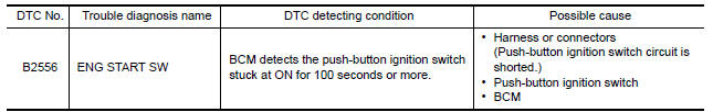
DTC CONFIRMATION PROCEDURE
1.PERFORM DTC CONFIRMATION PROCEDURE
1. Press push-button ignition switch under the following condition.
- Brake pedal: Not depressed
2. Release push-button ignition switch and wait 100 seconds or more.
3. Check DTC in Self Diagnostic Result mode of BCM using CONSULT.
Is DTC detected?
YES >> Go to SEC "Diagnosis Procedure".
NO >> Inspection End.
Diagnosis Procedure
Regarding Wiring Diagram information, refer to SEC "Wiring Diagram".
1.CHECK PUSH-BUTTON IGNITION SWITCH INPUT SIGNAL
1. Turn ignition switch OFF.
2. Disconnect push-button ignition switch connector.
3. Check voltage between push-button ignition switch harness connector and
ground. 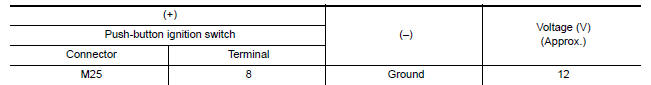
Is the inspection result normal?
YES >> GO TO 4.
NO >> GO TO 2.
2.CHECK PUSH-BUTTON IGNITION SWITCH CIRCUIT
1. Disconnect BCM connector and IPDM E/R connector.
2. Check continuity between push-button ignition switch harness connector and
BCM harness connector.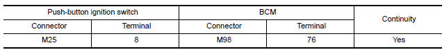
3. Check continuity between push-button ignition switch harness connector and
ground.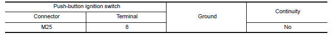
Is the inspection result normal?
YES >> GO TO 3.
NO >> Repair or replace harness.
3.REPLACE BCM
1. Replace BCM. Refer to BCS "Removal and Installation".
2. Perform initialization of BCM and registration of all Intelligent Keys using CONSULT.
>> Inspection End.
4.CHECK PUSH-BUTTON IGNITION SWITCH GROUND CIRCUIT
Check continuity between push-button ignition switch harness connector and
ground. 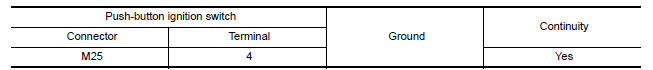
Is the inspection result normal?
YES >> GO TO 5.
NO >> Repair or replace harness.
5.CHECK PUSH-BUTTON IGNITION SWITCH
Refer to SEC "Component Inspection".
Is the inspection result normal?
YES >> GO TO 6.
NO >> Replace push-button ignition switch. Refer to SEC "Removal and Installation".
6.CHECK INTERMITTENT INCIDENT
Refer to GI "Intermittent Incident".
>> Inspection End.
Component Inspection
1.CHECK PUSH-BUTTON IGNITION SWITCH
1. Turn ignition switch OFF.
2. Disconnect push-button ignition switch connector.
3. Check continuity between push-button ignition switch terminals. 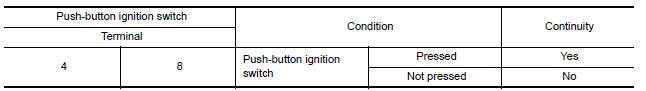
Is the inspection reult normal?
YES >> Inspection End.
NO >> Replace push-button ignition switch. Refer to SEC "Removal and Installation".
 B2555 Stop lamp
Other materials:
Meters and gauges
Type A (if so equipped)
1. Tachometer
2. Speedometer
3. Fuel gauge
4. Odometer
Twin trip odometer
Trip computer
5. Continuously Variable Transmission
(CVT) position indicator (if so equipped)
Automatic Transmission (A/T) position
indicator (if so equipped)
6. Instrument brightness con ...
Final drive
Exploded View
1. Differential side bearing outer race 2. Differential side bearing 3. Final
drive
: Replace the parts as a set.
Disassembly
Remove differential side bearings, using Tool (A) and suitable tool.
Tool number : ST33052000 ( - )
Assembly
Install differential sid ...
Categories
- Manuals Home
- Nissan Versa Owners Manual
- Nissan Versa Service Manual
- Video Guides
- Questions & Answers
- External Resources
- Latest Updates
- Most Popular
- Sitemap
- Search the site
- Privacy Policy
- Contact Us

0.0056