Nissan Versa (N17): B2615 Blower relay circuit
DTC Logic
DTC DETECTION LOGIC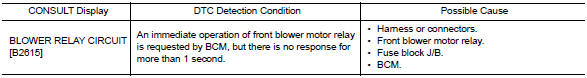
DTC CONFIRMATION PROCEDURE
1.PERFORM DTC CONFIRMATION PROCEDURE
1. Turn ignition switch ON, and wait for 1 second or more.
2. Check "Self-diagnosis result" with CONSULT.
Is DTC detected?
YES >> Go to PCS "Diagnosis Procedure".
NO >> Inspection End.
Diagnosis Procedure
Regarding Wiring Diagram information, refer to PCS "Wiring Diagram".
1. CHECK BLOWER MOTOR RELAY POWER SUPPLY CIRCUIT
1. Turn ignition switch OFF.
2. Disconnect blower motor relay.
3. Disconnect BCM connector M19.
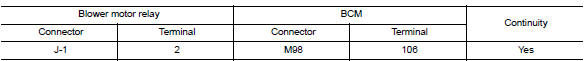
4. Check continuity between blower motor relay connector J-1 terminal 2 and
BCM connector M98 terminal
106.
5. Check continuity between Blower motor relay connector J-1 terminal 2 and
ground.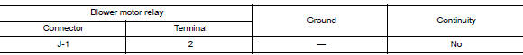
Is the inspection result normal?
YES >> GO TO 2.
NO >> Repair or replace harness or connectors.
2. CHECK BLOWER MOTOR RELAY GROUND CIRCUIT
1. Check continuity between Blower motor relay connector J-1 terminal 1 and
ground.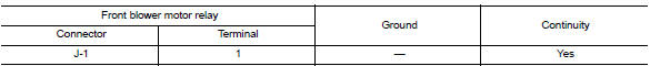
Is the inspection result normal?
YES >> GO TO 3.
NO >> Repair or replace harness or connectors.
3. CHECK BLOWER MOTOR RELAY
Perform the relay component inspection. Refer to HAC "Component Inspection (Blower Relay)".
Is the inspection result normal?
YES >> GO TO 4.
NO >> Replace blower motor relay.
4. CHECK BLOWER MOTOR RELAY POWER SUPPLY (BCM)
Check voltage between BCM connector M98 terminal 106 and ground.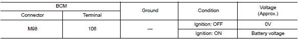
Is the inspection result normal?
YES >> Refer to GI "Intermittent Incident".
NO >> Replace BCM. Refer to BCS "Removal and Installation".
Component Inspection
1.CHECK BLOWER RELAY
1. Turn blower switch OFF.
2. Remove blower relay.
3. Check the continuity between blower relay terminals.
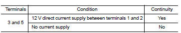
Is the inspection result normal?
YES >> Inspection End.
NO >> Replace blower relay
 B2614 ACC Relay circuit
Other materials:
B terminal circuit
Description
Terminal "B" is constantly supplied with battery power.
Diagnosis Procedure
Regarding Wiring Diagram information, refer to STR, "Wiring Diagram - With
Intelligent Key System" or
STR, "Wiring Diagram - Without Intelligent Key System".
CAUTION: Perform diagnosis ...
Warning function
WARNING FUNCTION : System Description
OPERATION DESCRIPTION
The warning function are as per the following items and are given to the user
as warning information and
warnings using combinations of Intelligent Key warning buzzer, combination meter
buzzer, KEY warning lamp,
shift P warning lamp ...
Categories
- Manuals Home
- Nissan Versa Owners Manual
- Nissan Versa Service Manual
- Video Guides
- Questions & Answers
- External Resources
- Latest Updates
- Most Popular
- Sitemap
- Search the site
- Privacy Policy
- Contact Us

0.0074