Nissan Versa (N17): B26F1 Ignition relay
DTC Logic
DTC DETECTION LOGIC
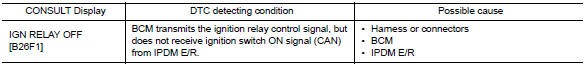
DTC CONFIRMATION PROCEDURE
1.PERFORM DTC CONFIRMATION PROCEDURE
1. Turn ignition switch ON, and wait for 2 seconds or more.
2. Check "Self-diagnosis result" with CONSULT.
Is DTC detected?
YES >> Go to PCS "Diagnosis Procedure".
NO >> Inspection End.
Diagnosis Procedure
Regarding Wiring Diagram information, refer to PCS "Wiring Diagram".
1.CHECK IPDM E/R SELF-DIAGNOSTIC RESULT
1. Turn ignition switch ON.
2. Erase the DTC of IPDM E/R.
3. Turn ignition switch OFF.
4. Turn ignition switch ON and check the DTC again.
Is DTC detected?
YES >> Repair or replace the malfunctioning part. Refer to BCS "DTC Index".
NO >> GO TO 2.
2.CHECK IGNITION RELAY-1 CONTROL SIGNAL (IPDM E/R)
Check voltage between BCM harness connector and ground.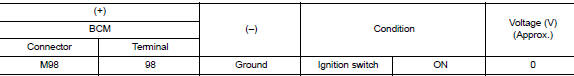
Is the inspection result normal?
YES >> GO TO 3.
NO >> Replace BCM. Refer to BCS "Removal and Installation".
3.CHECK IGNITION RELAY-1 CONTROL SIGNAL CIRCUIT (IPDM E/R)
1. Turn ignition switch OFF.
2. Disconnect BCM and IPDM E/R connectors.
3. Check continuity between BCM harness connector and IPDM E/R harness
connector.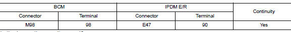
Is the inspection result normal?
YES >> Replace IPDM E/R.
NO >> Repair or replace harness.
 B261A Push-button ignition switch
Other materials:
Remote keyless entry system
REMOTE KEYLESS ENTRY SYSTEM : System
Diagram
REMOTE KEYLESS ENTRY SYSTEM : System
Description
The remote keyless entry system can be locked and unlocked by pressing door
lock and unlock button of keyfob.
DOOR LOCK AND UNLOCK OPERATION
When door lock and unlock button of keyfob is ...
Washer pump
Exploded View
1. Washer tank 2. Front washer tube 3. Washer pump
4. Seal Front
Removal and Installation
REMOVAL
1. Remove fender protector. Refer to EXT "Removal and Installation".
2. Disconnect the harness connector from the washer pump.
3. Remove front washer tube.
4. Remov ...
Categories
- Manuals Home
- Nissan Versa Owners Manual
- Nissan Versa Service Manual
- Video Guides
- Questions & Answers
- External Resources
- Latest Updates
- Most Popular
- Sitemap
- Search the site
- Privacy Policy
- Contact Us

0.0057