Nissan Versa (N17): P0075 IVT control solenoid valve
DTC Logic
DTC DETECTION LOGIC
| DTC No. | Trouble diagnosis name | DTC detecting condition | Possible cause |
| P0075 | Intake valve timing control solenoid valve circuit | An improper voltage is sent to the ECM through intake valve timing control solenoid valve. |
|
DTC CONFIRMATION PROCEDURE
1.PRECONDITIONING
If DTC Confirmation Procedure has been previously conducted, always perform the following procedure before conducting the next test.
- Turn ignition switch OFF and wait at least 10 seconds.
- Turn ignition switch ON.
- Turn ignition switch OFF and wait at least 10 seconds.
>> GO TO2.
2.PERFORM DTC CONFIRMATION PROCEDURE
- Start engine and let it idle for 5 seconds.
- Check 1st trip DTC.
Is 1st trip DTC detected?
YES >> Go to EC, "Diagnosis Procedure".
NO >> INSPECTION END
Diagnosis Procedure
1.CHECK INTAKE VALVE TIMING CONTROL SOLENOID VALVE POWER SUPPLY CIRCUIT
- Turn ignition switch OFF.
- Disconnect intake valve timing (IVT) control solenoid valve harness connector.
- Turn ignition switch ON.
- Check the voltage between intake valve timing control solenoid valve harness connector and ground
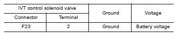
Is the inspection result normal?
YES >> GO TO 3.
NO >> GO TO 2.
2.DETECT MALFUNCTIONING PART
Check the following.
- Harness for open or short between intake valve timing control solenoid valve and IPDM E/R
>> Repair open circuit or short to ground or short to power in harness or connectors.
3.CHECK INTAKE VALVE TIMING CONTROL SOLENOID VALVE OUTPUT SIGNAL CIRCUIT FOR OPEN AND SHORT
- Turn ignition switch OFF.
- Disconnect ECM harness connector.
- Check the continuity between intake valve timing control solenoid valve harness connector and ECM harness connector.
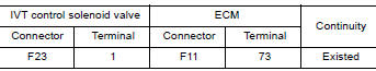
4. Also check harness for short to ground and short to power.
Is the inspection result normal?
YES >> GO TO 4.
NO >> Repair open circuit or short to ground or short to power in harness or connectors.
4.CHECK INTAKE VALVE TIMING CONTROL SOLENOID VALVE
Refer to EM, "Exploded View".
Is the inspection result normal?
YES >> GO TO 5.
NO >> Replace intake valve timing control solenoid valve. Refer to EM, "Exploded View".
5.CHECK INTERMITTENT INCIDENT
Refer to GI, "Intermittent Incident".
>> INSPECTION END
Component Inspection
1.CHECK INTAKE VALVE TIMING CONTROL SOLENOID VALVEI
- Turn ignition switch OFF.
- Disconnect intake valve timing control solenoid valve harness connector.
- Check resistance between intake valve timing control solenoid valve terminals as follows.
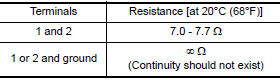
Is the inspection result normal?
YES >> GO TO 2.
NO >> Replace intake valve timing control solenoid valve. Refer to EM, "Exploded View".
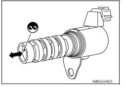
2.CHECK INTAKE VALVE TIMING CONTROL SOLENOID VALVEII
- Remove intake valve timing control solenoid valve. Refer to EM, "Exploded View".
- Apply 12 V between intake valve timing control solenoid valve
terminals 1 and 2, and then interrupt it. Make sure that the
plunger moves as shown in the figure.
CAUTION: Do not apply 12 V continuously for 5 seconds or more.
Doing so may result in damage to the coil in intake valve timing control solenoid valve.
NOTE: Always replace Oring when intake valve timing control solenoid valve is removed.
Is the inspection result normal?
YES >> INSPECTION END
NO >> Replace intake valve timing control solenoid valve.
 P0037, P0038 HO2s2 heater
Other materials:
Brake and clutch (if so equipped) fluid
For additional information on brake fluid specification,
refer to "Recommended fluids/lubricants
and capacities" in the "Technical and consumer
information" section of this manual.
WARNING
Use only new fluid from a sealed container.
Old, inferior or contaminated
fluid may damage the br ...
Key interlock cable
Exploded View
1. CVT shift selector assembly 2. Key interlock cable
A: Key cylinder B: Lock plate C: Clip
Removal and Installation
REMOVAL
CAUTION:
Always apply the parking brake before performing removal and installation.
Move the shift selector to the "N" position.
Remove the shi ...
Categories
- Manuals Home
- Nissan Versa Owners Manual
- Nissan Versa Service Manual
- Video Guides
- Questions & Answers
- External Resources
- Latest Updates
- Most Popular
- Sitemap
- Search the site
- Privacy Policy
- Contact Us

0.007