Nissan Versa (N17): P0037, P0038 HO2s2 heater
DTC Logic
DTC DETECTION LOGIC
| DTC No. | Trouble diagnosis name (Trouble diagnosis content) | DTC detecting condition | Possible cause |
| P0037 | HO2 HTR (B1) (Heated oxygen sensor 2 heater control circuit low) | The current amperage in the heated oxygen sensor 2
heater circuit is out of the normal range.
(An excessively low voltage signal is sent to ECM through the heated oxygen sensor 2 heater.) |
|
| P0038 | HO2 HTR (B1) (Heated oxygen sensor 2 heater control circuit high) | The current amperage in the heated oxygen sensor 2
heater circuit is out of the normal range.
(An excessively high voltage signal is sent to ECM through the heated oxygen sensor 2 heater.) |
|
DTC CONFIRMATION PROCEDURE
1.PRECONDITIONING
If DTC Confirmation Procedure has been previously conducted, always perform the following procedure before conducting the next test.
- Turn ignition switch OFF and wait at least 10 seconds.
- Turn ignition switch ON.
- Turn ignition switch OFF and wait at least 10 seconds.
TESTING CONDITION: Before performing the following procedure, confirm that battery voltage is more than 11 V at idle.
>> GO TO 2.
2.PERFORM DTC CONFIRMATION PROCEDURE
 With CONSULT
- Turn ignition switch ON and select "DATA MONITOR" mode of "ENGINE" using CONSULT.
- Start engine and warm it up to normal operating temperature.
- Turn ignition switch OFF and wait at least 10 seconds.
- Start engine and keep the engine speed between 3,500 and 4,000 rpm for at least 1 minute under no load.
- Let engine idle for 1 minute.
- Check 1st trip DTC.
 With GST
Follow the procedure "With CONSULT" above.
Is 1st trip DTC detected?
YES >> Proceed to EC, "Diagnosis Procedure".
NO >> INSPECTION END
Diagnosis Procedure
1.CHECK HO2S2 POWER SUPPLY CIRCUIT
- Turn ignition switch OFF.
- Disconnect heated oxygen sensor 2 (HO2S2) harness connector.
- Turn ignition switch ON.
- Check the voltage between HO2S2 harness connector and ground.
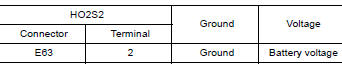
Is the inspection result normal?
YES >> GO TO 2.
NO >> Repair or replace errordetected parts.
2.CHECK HO2S2 OUTPUT SIGNAL CIRCUIT
- Turn ignition switch OFF.
- Disconnect ECM harness connector.
- Check the continuity between HO2S2 harness connector and ECM harness connector.
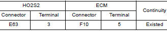
4. Also check harness for short to ground and short to power.
Is the inspection result normal?
YES >> GO TO 3.
NO >> Repair or replace errordetected parts.
3.CHECK HEATED OXYGEN SENSOR 2 HEATER
Check the heated oxygen sensor 2 heater. Refer to EC, "Component Inspection".
Is the inspection result normal?
YES >> Check intermittent incident. Refer to GI, "Intermittent Incident".
NO >> GO TO 4.
4.REPLACE HEATED OXYGEN SENSOR 2
Replace heated oxygen sensor 2. Refer to EX, "Exploded View".
CAUTION: - Discard any sensor which has been dropped from a height of more than 0.5 m (19.7 in) onto a hard surface such as a concrete floor; use a new one.
- Before installing new sensor, clean exhaust system threads using Oxygen Sensor Thread Cleaner [commercial service tool (J4389718 or J4389712)] and approved Antiseize Lubricant (commercial service tool).
>> INSPECTION END
Component Inspection
1.CHECK HEATED OXYGEN SENSOR 2 HEATER
- Turn ignition switch OFF.
- Disconnect heated oxygen sensor 2 (HO2S2) harness connector.
- Check resistance between HO2S2 terminals as per the following.
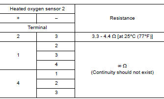
Is the inspection result normal?
YES >> INSPECTION END
NO >> GO TO 2.
2.REPLACE HEATED OXYGEN SENSOR 2
Replace heated oxygen sensor 2. Refer to EX, "Exploded View".
CAUTION:
- Discard any sensor which has been dropped from a height of more than 0.5 m (19.7 in) onto a hard surface such as a concrete floor; use a new one.
- Before installing new sensor, clean exhaust system threads using Oxygen Sensor Thread Cleaner [commercial service tool (J4389718 or J4389712)] and approved Antiseize Lubricant (commercial service tool).
>> INSPECTION END
 P0031, P0032 A/F sensor 1 heater
Other materials:
Break-in schedule
CAUTION
During the first 1,200 miles (2,000 km),
follow these recommendations to obtain
maximum engine performance and ensure
the future reliability and economy of your
new vehicle. Failure to follow these recommendations
may result in shortened
engine life and reduced engine
performance.
...
P0846 Transmission fluid pressure
SEN/SW B
DTC Logic
DTC DETECTION LOGIC
DTC
Trouble diagnosis name
DTC detection condition
Possible causes
P0846
Transmission Fluid Pressure
Sensor/Switch B Circuit
Range/Performance
The detection conditions continuously for 5
seconds or more under the following diagn ...
Categories
- Manuals Home
- Nissan Versa Owners Manual
- Nissan Versa Service Manual
- Video Guides
- Questions & Answers
- External Resources
- Latest Updates
- Most Popular
- Sitemap
- Search the site
- Privacy Policy
- Contact Us

0.0069