Nissan Versa (N17): P0101 MAF sensor
DTC Logic
DTC DETECTION LOGIC
NOTE: If DTC P0101 is displayed with other DTC, first perform the trouble diagnosis for other DTC.
| DTC No. | Trouble diagnosis name (Trouble diagnosis content) | DTC detecting condition | Possible cause |
| P0101 | MAF SEN/CIRCUITB1 [Mass air flow (MAF) sensor circuit range/performance] |
|
|
DTC CONFIRMATION PROCEDURE
1.PRECONDITIONING
If DTC CONFIRMATION PROCEDURE has been previously conducted, always perform the following procedure before conducting the next test.
- Turn ignition switch OFF and wait at least 10 seconds.
- Turn ignition switch ON.
- Turn ignition switch OFF and wait at least 10 seconds.
>> GO TO 2.
2.PERFORM DTC CONFIRMATION PROCEDURE
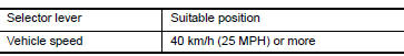
- Start engine and warm it up to normal operating temperature.
- Drive the vehicle for at least 5 seconds under the following conditions: CAUTION: Always drive vehicle at safe speed.
NOTE:
- The gear must be fixed while driving the vehicle.
- Keep the accelerator pedal as steady as possible during cruising.
3. Check 1st trip DTC.
Is 1st trip DTC detected?
YES >> Proceed to EC178, "Diagnosis Procedure".
NO >> INSPECTION END
Diagnosis Procedure
1.CHECK INTAKE SYSTEM
Check the following for connection.
- Air duct
- Vacuum hoses
- Intake air passage between air duct and intake manifold
Is the inspection result normal?
YES >> GO TO 2.
NO >> Reconnect the parts.
2.CHECK GROUND CONNECTION
- Turn ignition switch OFF.
Check ground connection E. Refer to Ground Inspection in GI, "Circuit Inspection".
Is the inspection result normal?
YES >> GO TO 3.
NO >> Repair or replace ground connection.
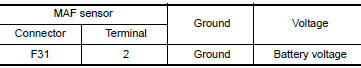
3.CHECK MASS AIR FLOW (MAF) SENSOR POWER SUPPLY CIRCUIT
- Disconnect MAF sensor harness connector.
- Turn ignition switch ON.
- Check the voltage between MAF sensor harness connector and ground.
Is the inspection result normal?
YES >> GO TO 5.
NO >> GO TO 4.
4.DETECT MALFUNCTIONING PART
Check the following.
- Harness connectors E, F
- Harness for open or short between mass air flow sensor and ECM
- Harness for open or short between mass air flow sensor and IPDM E/R
>> Repair open circuit or short to ground or short to power in harness or connectors.
5.CHECK MAF SENSOR GROUND CIRCUIT FOR OPEN AND SHORT
- Turn ignition switch OFF.
- Disconnect ECM harness connector.
- Check the continuity between MAF sensor harness connector and ECM harness connector.
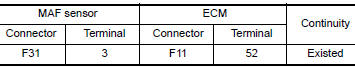
4. Also check harness for short to ground and short to power.
Is the inspection result normal?
YES >> GO TO 6.
NO >> Repair open circuit or short to ground or short to power in harness or connectors.
6.CHECK MAF SENSOR INPUT SIGNAL CIRCUIT FOR OPEN AND SHORT
1. Check the continuity between MAF sensor harness connector and ECM harness connector.
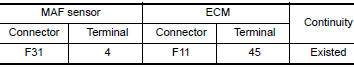
2. Also check harness for short to ground and short to power.
Is the inspection result normal?
YES >> GO TO 7.
NO >> Repair open circuit or short to ground or short to power in harness or connectors.
7.CHECK INTAKE AIR TEMPERATURE SENSOR
Check the intake air temperature sensor. Refer to EC, "Component Inspection".
Is the inspection result normal?
YES >> GO TO 8.
NO >> Replace MAF sensor (with intake air temperature sensor). Refer to EM, "Removal and Installation".
8.CHECK EVAP CONTROL SYSTEM PRESSURE SENSOR
Check the EVAP control system pressure sensor. Refer to EC, "Component Inspection".
Is the inspection result normal?
YES >> GO TO 9.
NO >> Replace EVAP control system pressure sensor. Refer to FL, "Removal and Installation".
9.CHECK MAF SENSOR
Check the MAF sensor. Refer to EC, "Component Inspection".
Is the inspection result normal?
YES >> Check intermittent incident. Refer to GI, "Intermittent Incident".
NO >> Replace MAF sensor. Refer to EM, "Removal and Installation".
Component Inspection
1.CHECK MASS AIR FLOW SENSORI
 With CONSULT
- Turn ignition switch OFF.
- Reconnect all harness connectors disconnected.
- Start engine and warm it up to normal operating temperature.
- Connect CONSULT and select "DATA MONITOR" mode of "ENGINE".
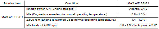
- Select "MAS A/F SEB1" and check indication.
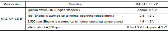
*: Check for linear voltage rise in response to engine being increased to about 4,000 rpm.
 Without CONSULT
- Turn ignition switch OFF.
- Reconnect all harness connectors disconnected.
- Start engine and warm it up to normal operating temperature.
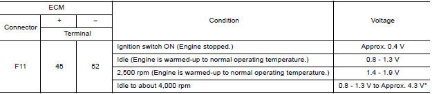
- Check the voltage between ECM harness connector and ground.
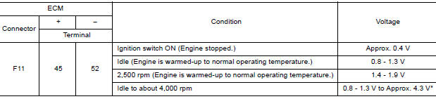
*: Check for linear voltage rise in response to engine being increased to about 4,000 rpm.
Is the inspection result normal?
YES >> INSPECTION END
NO >> GO TO 2.
2.CHECK FOR THE CAUSE OF UNEVEN AIR FLOW THROUGH MASS AIR FLOW SENSOR
- Turn ignition switch OFF.
- Check for the cause of uneven air flow through mass air flow sensor. Refer to the following.
- Crushed air ducts
- Malfunctioning seal of air cleaner element
- Uneven dirt of air cleaner element
- Improper specification of intake air system parts
Is the inspection result normal?
YES >> GO TO 4.
NO >> GO TO 3.
3.CHECK MASS AIR FLOW SENSORII
With CONSULT
- Repair or replace malfunctioning part.
- Start engine and warm it up to normal operating temperature.
- Connect CONSULT and select "DATA MONITOR" mode of "ENGINE".
- Select "MAS A/F SEB1" and check indication.
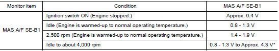
*: Check for linear voltage rise in response to engine being increased to about 4,000 rpm.
Without CONSULT
- Repair or replace malfunctioning part.
- Start engine and warm it up to normal operating temperature.
- Check the voltage between ECM harness connector and ground.
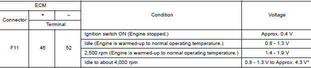
*: Check for linear voltage rise in response to engine being increased to about 4,000 rpm.
Is the inspection result normal?
YES >> INSPECTION END
NO >> GO TO 4.
4.CHECK MASS AIR FLOW SENSORIII
With CONSULT
- Turn ignition switch OFF.
- Disconnect mass air flow sensor harness connector and reconnect it again.
- Start engine and warm it up to normal operating temperature.
- Connect CONSULT and select "DATA MONITOR" mode of "ENGINE".
- Select "MAS A/F SEB1" and check indication.
*: Check for linear voltage rise in response to engine being increased to about 4,000 rpm.
Without CONSULT
- Turn ignition switch OFF.
- Disconnect mass air flow sensor harness connector and reconnect it again.
- Start engine and warm it up to normal operating temperature.
- Check the voltage between ECM harness connector and ground.
*: Check for linear voltage rise in response to engine being increased to about 4,000 rpm.
Is the inspection result normal?
YES >> INSPECTION END
NO >> Clean or replace mass air flow sensor. Refer to EM, "Removal and Installation".
 P0078 EVT control solenoid valve
Other materials:
Thermostat
Exploded View
1. Radiator hose (lower) 2. Water inlet 3. Rubber ring
4. Thermostat A. To radiator
Removal and Installation
WARNING:
Do not remove the radiator cap when the engine is hot. Serious burns
could occur from highpressure
engine coolant escaping from the radiator. Wrap a thick cl ...
Power supply and ground circuit
Diagnosis Procedure
1.CHECK GROUND CONNECTION
Turn ignition switch OFF.
Check ground connection E. Refer to Ground Inspection in GI, "Circuit
Inspection".
Is the inspection result normal?
YES >> GO TO 2.
NO >> Repair or replace ground connection.
2.CHECK ECM G ...
Categories
- Manuals Home
- Nissan Versa Owners Manual
- Nissan Versa Service Manual
- Video Guides
- Questions & Answers
- External Resources
- Latest Updates
- Most Popular
- Sitemap
- Search the site
- Privacy Policy
- Contact Us

0.0066