Nissan Versa (N17): Ecm
Reference Value
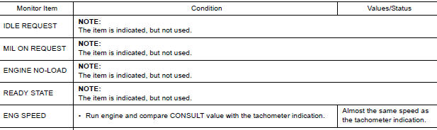
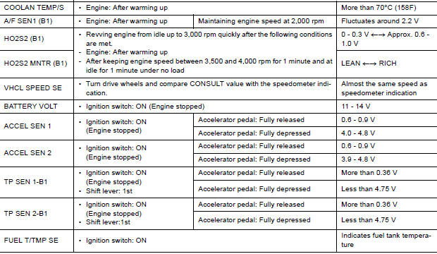
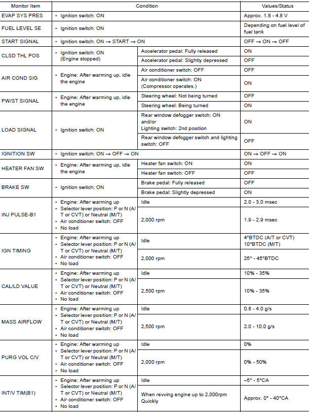
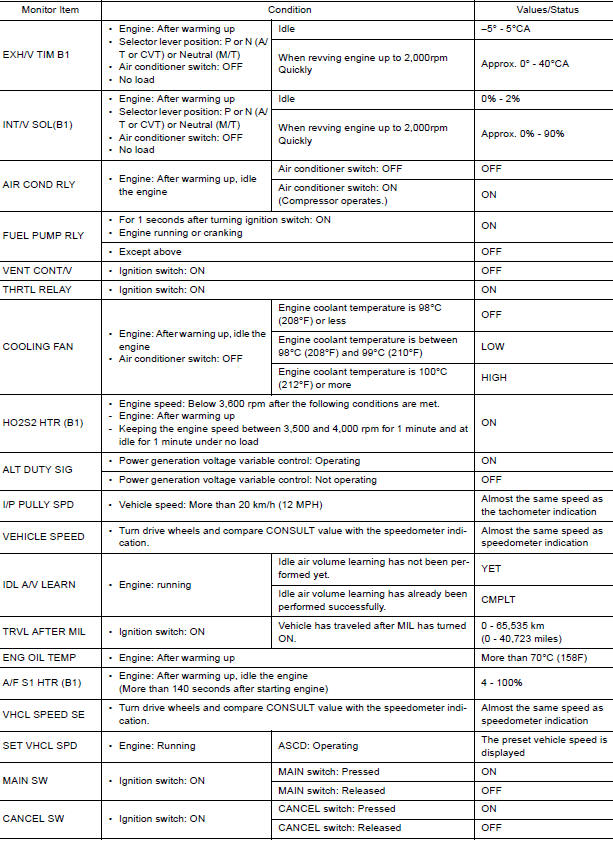
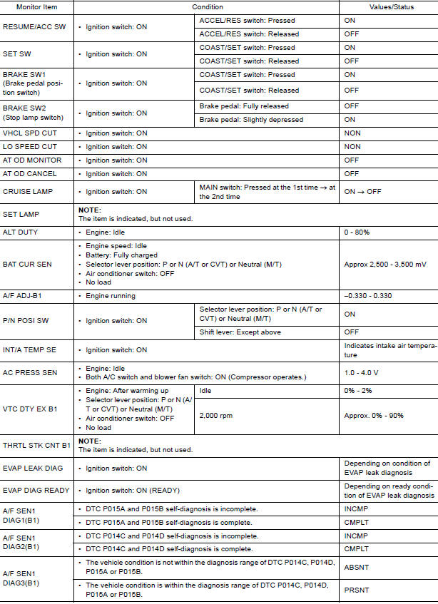
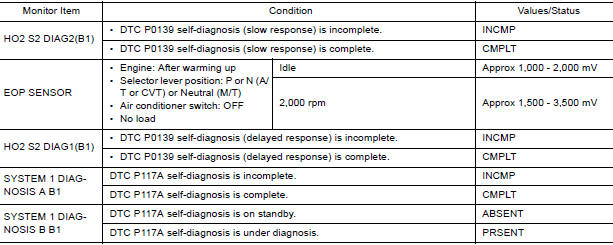
VALUES ON THE DIAGNOSIS TOOL
NOTE:
- The following table includes information (items) inapplicable to this vehicle. For information (items) applicable to this vehicle, refer to CONSULT display items.
- Numerical values in the following table are reference values.
- These values are input/output values that ECM receives/transmits and
may differ from actual operations.
Example: The ignition timing shown by the timing light may differ from the ignition timing displayed on the data monitor.
This occurs because the timing light shows a value calculated by ECM according to signals received from the camshaft position sensor and other sensors related to ignition timing.
- For outlines of following items.
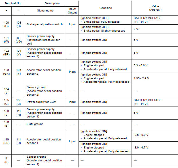
*: Accelerator pedal position sensor 2 signal and throttle position sensor 2 signal are converted by ECM internally.
Thus, they differ from ECM terminals voltage signal.
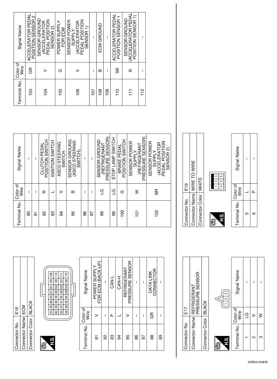
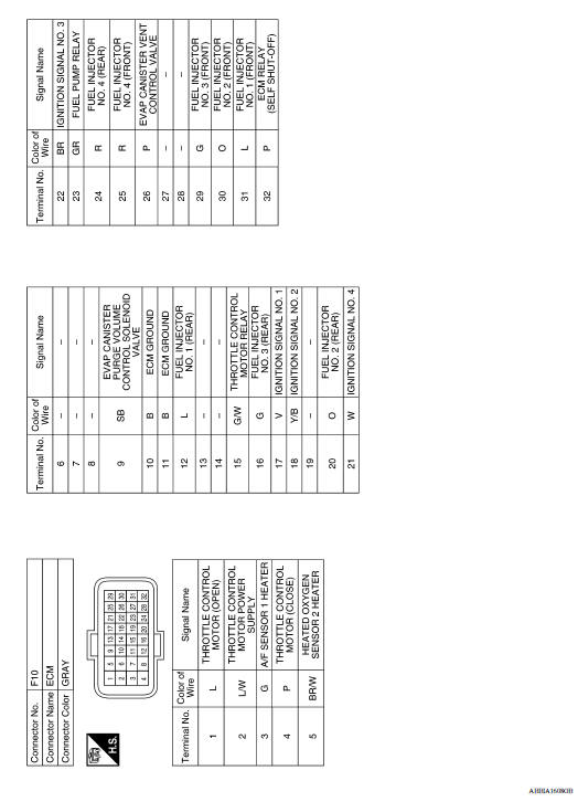
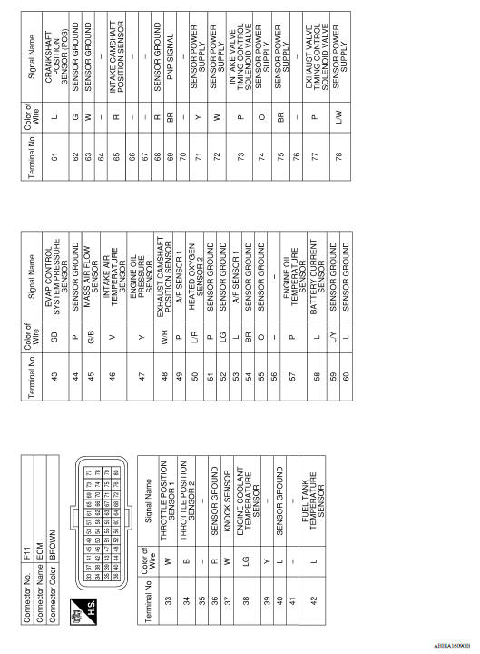
TERMINAL LAYOUT
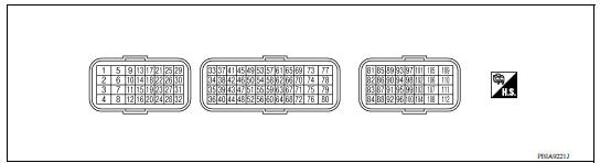
PHYSICAL VALUES
NOTE:
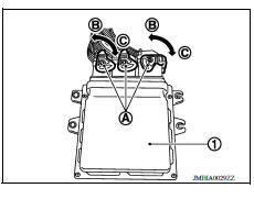
- ECM is located in the engine room left side near battery.
- When disconnecting ECM harness connector (A), loosen (C) it with levers as far as they will go as shown in the figure. ECM (1) Fasten (B)
- Connect a breakout box and harness adapter between the ECM
and ECM harness connector.
Use extreme care not to touch 2 pins at one time.
Data is for comparison and may not be exact.
- Specification data are reference values and are measured between each terminals.
- Pulse signal is measured by CONSULT.
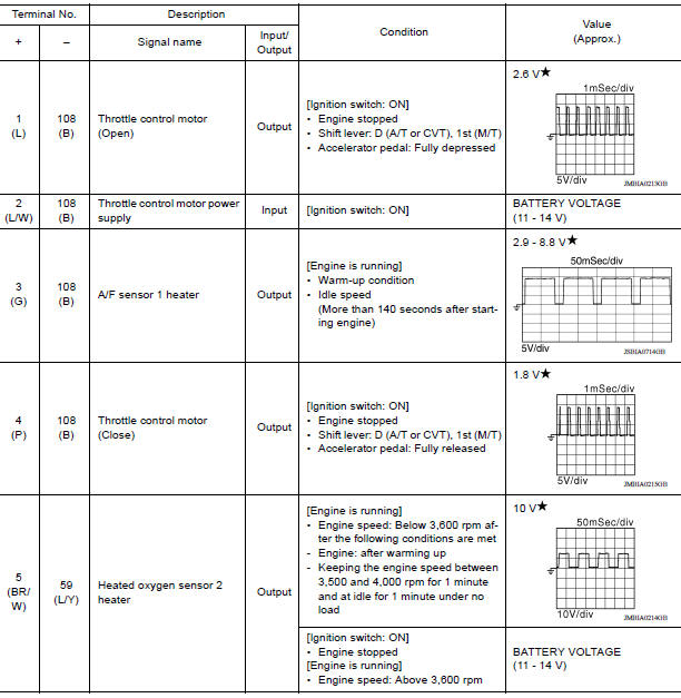
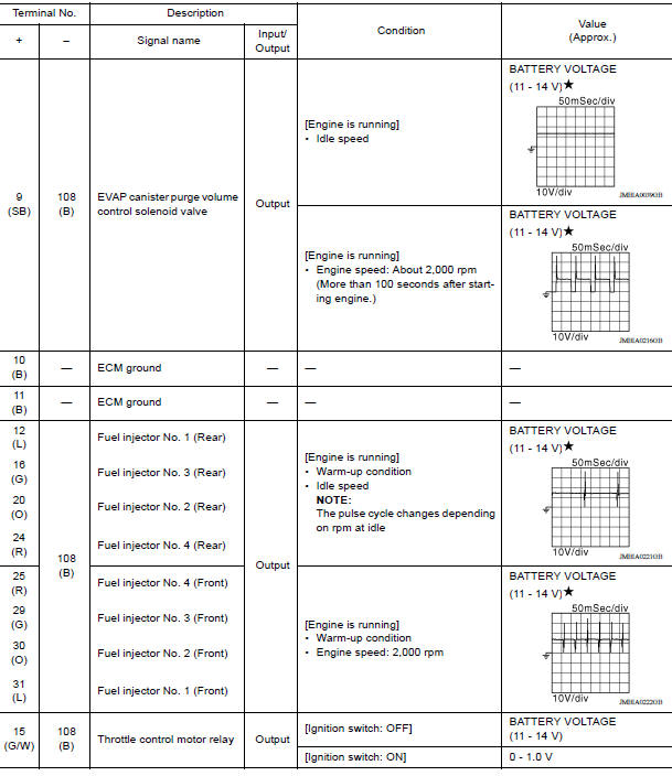
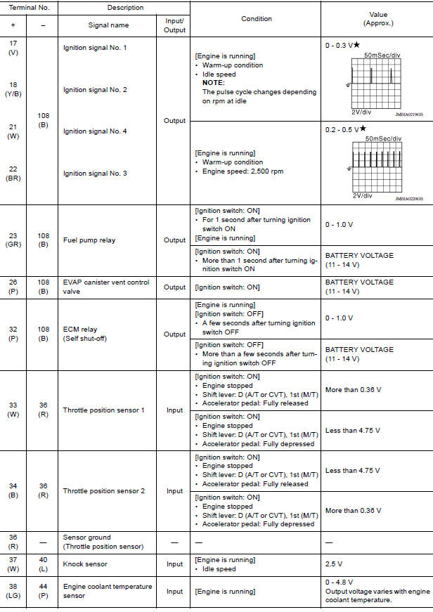
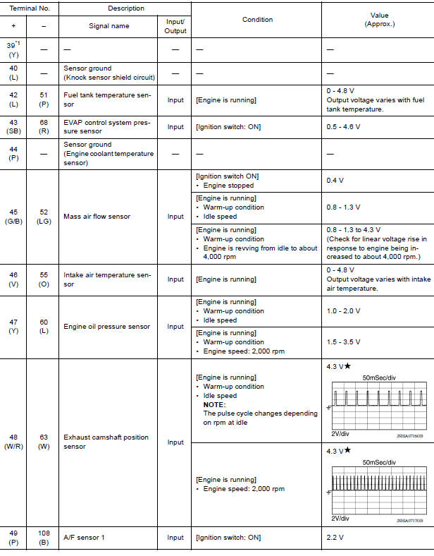
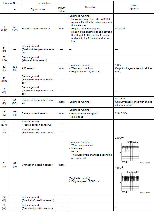
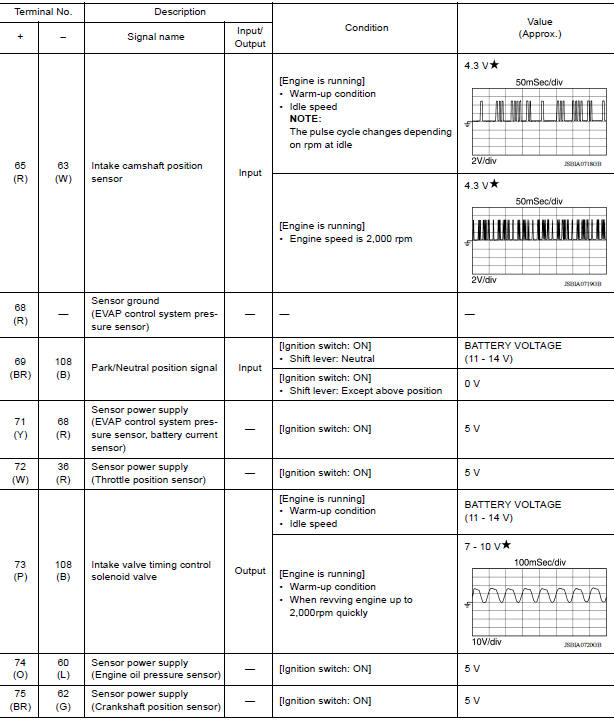
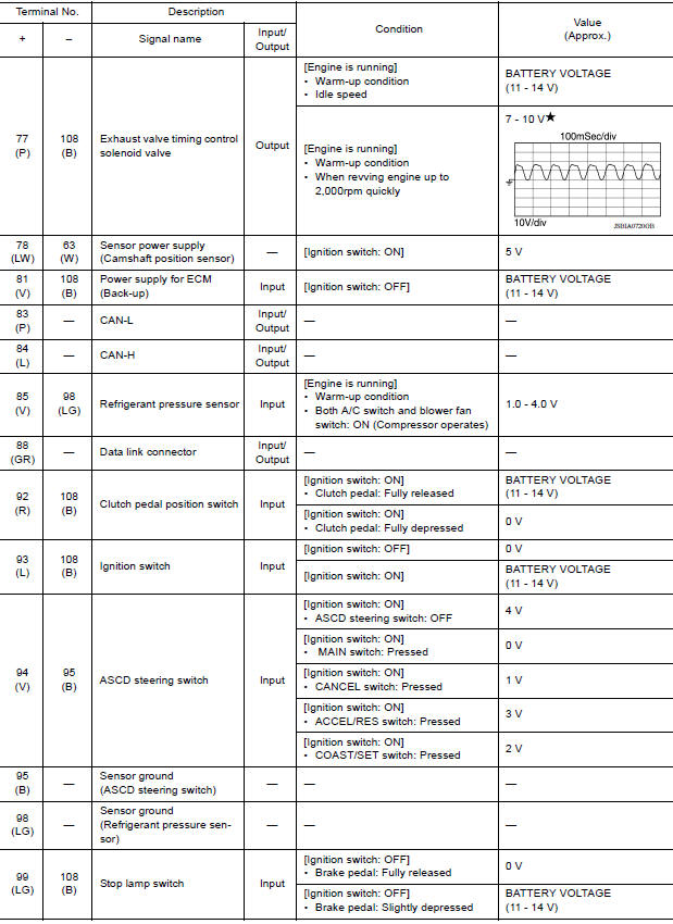
 : Average voltage for pulse
signal (Actual pulse signal can be confirmed by oscilloscope.)
*1: Not used
*2: Before measuring the terminal voltage, confirm that the battery is fully
charged.
: Average voltage for pulse
signal (Actual pulse signal can be confirmed by oscilloscope.)
*1: Not used
*2: Before measuring the terminal voltage, confirm that the battery is fully
charged.
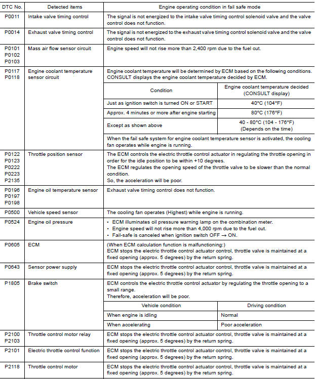
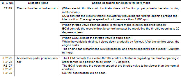
Fail Safe
NON DTC RELATED ITEM
| Detected items | Engine operating condition in failsafe mode | Remarks |
| Malfunction indicator lamp circuit | Engine speed will not rise more than 2,500 rpm due to the fuel cut | When there is an open circuit on MIL circuit, the ECM cannot warn
the
driver by lighting up MIL when there is malfunction on engine control
system.
Therefore, when electrical controlled throttle and part of ECM related diagnoses are continuously detected as NG for 5 trips, ECM warns the driver that engine control system malfunctions and MIL circuit is open by means of operating fail safe function. The fail safe function also operates when above diagnoses except MIL circuit are detected and demands the driver to repair the malfunction. |
DTC RELATED ITEM
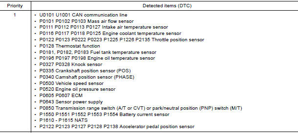
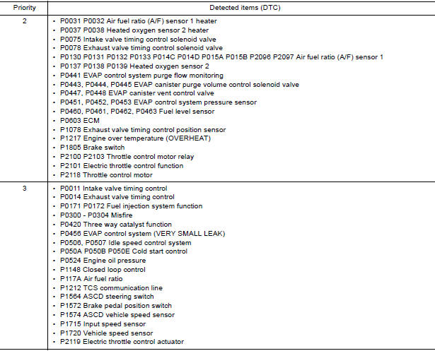
DTC Inspection Priority Chart
If some DTCs are displayed at the same time, perform inspections one by one based on the following priority chart.
DTC Index
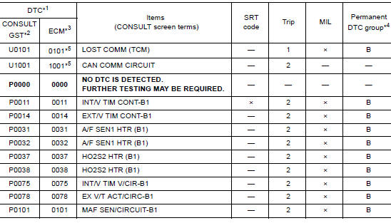
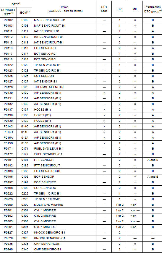
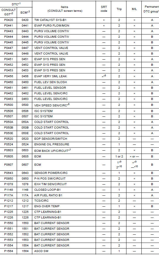
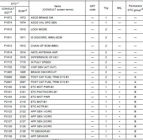
*1: 1st trip DTC No. is the same as DTC No.
*2: This number is prescribed by SAE J1979/ ISO 150315.
*3: In Diagnostic Test Mode II (Selfdiagnostic results), this number is controlled by NISSAN.
*4: Refer to EC, "Description".
*5: The troubleshooting for this DTC needs CONSULT.
*6: When the failsafe operations for both selfdiagnoses occur, the MIL illuminates.
*7: This selfdiagnosis is not for ECM power supply circuit, even though "ECM BACK UP/CIRCUIT" is displayed on CONSULT screen.
*8: SRT code will not be set if the selfdiagnostic result is NG.
*9: A/T models or CVT models.
*10: M/T models.
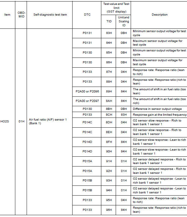
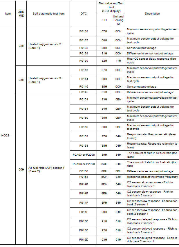
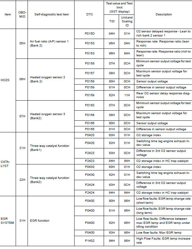
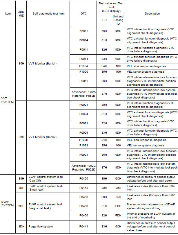
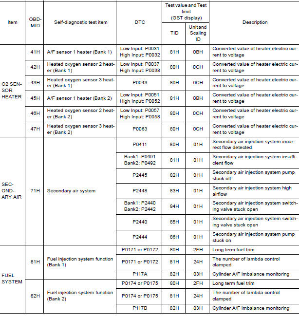
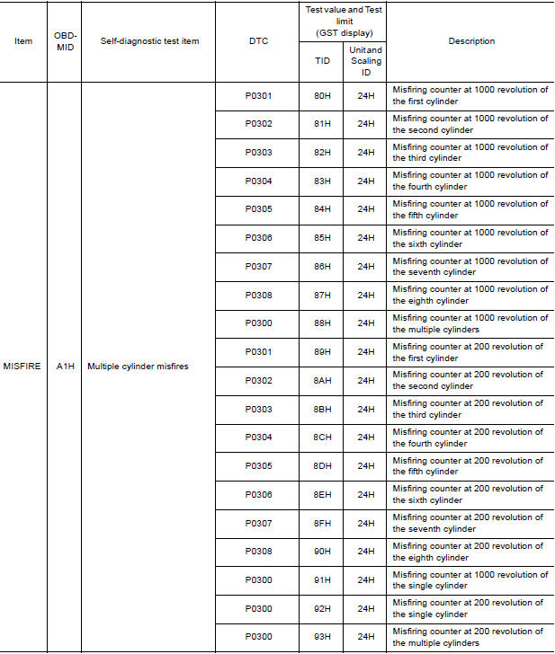
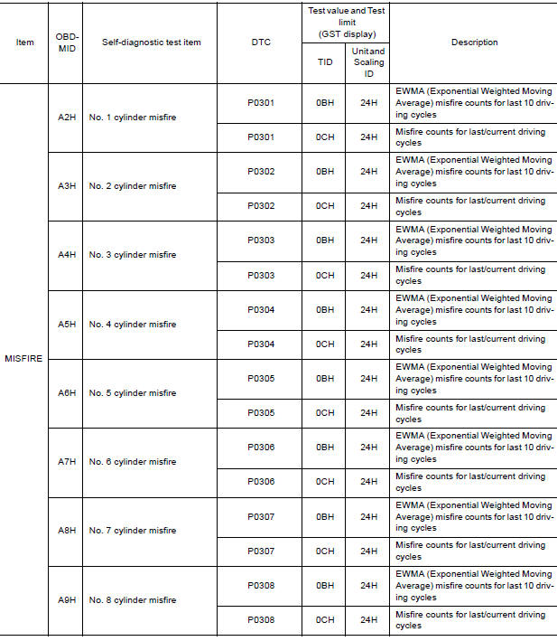
Test Value and Test Limit
The following is the information specified in Service $06 of SAE J1979/ISO 150315.
The test value is a parameter used to determine whether a system/circuit diagnostic test is OK or NG while being monitored by the ECM during selfdiagnosis. The test limit is a reference value which is specified as the maximum or minimum value and is compared with the test value being monitored.
These data (test value and test limit) are specified by On Board Monitor ID (OBDMID), Test ID (TID), Unit and Scaling ID and can be displayed on the GST screen.
The items of the test value and test limit will be displayed with GST screen which items are provided by the ECM. (e.g., if bank 2 is not applied on this vehicle, only the items of bank 1 are displayed)
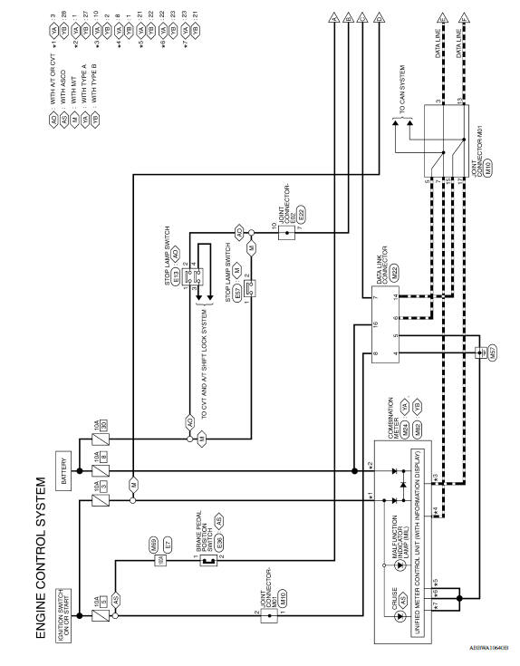
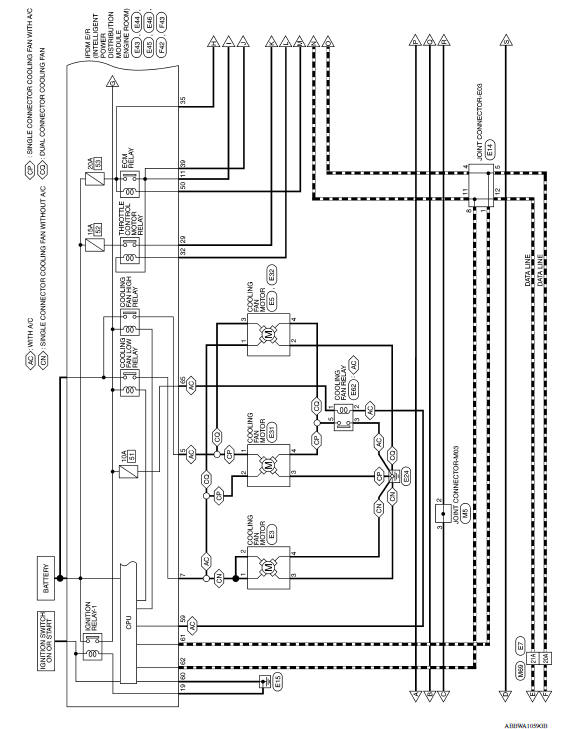
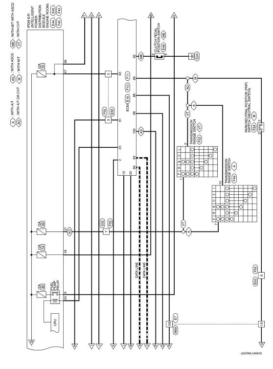
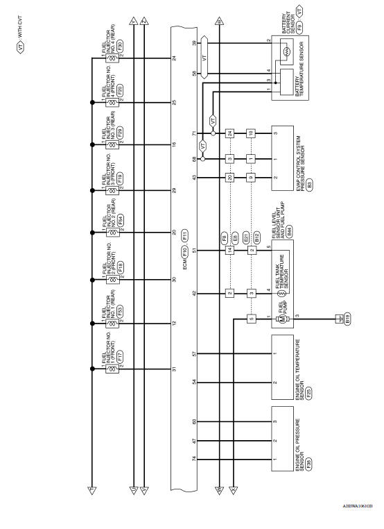
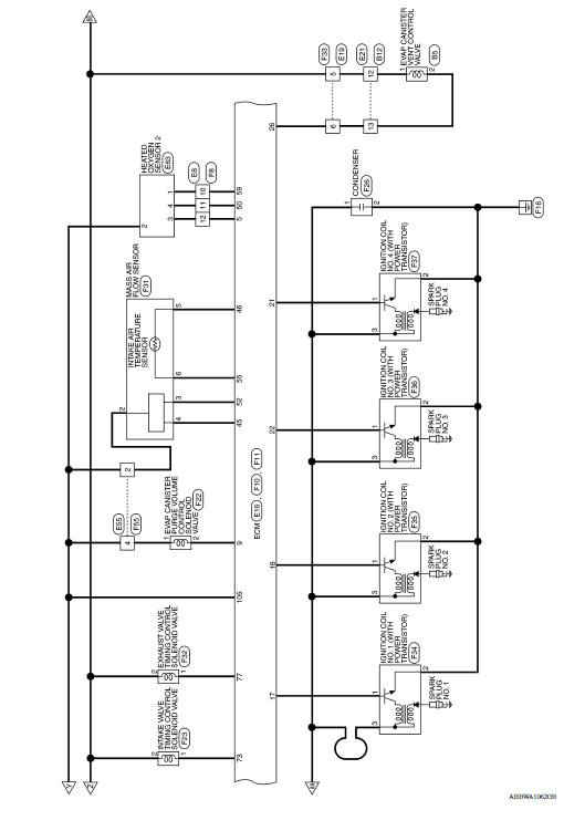
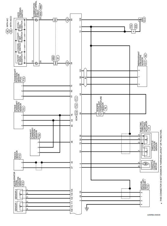
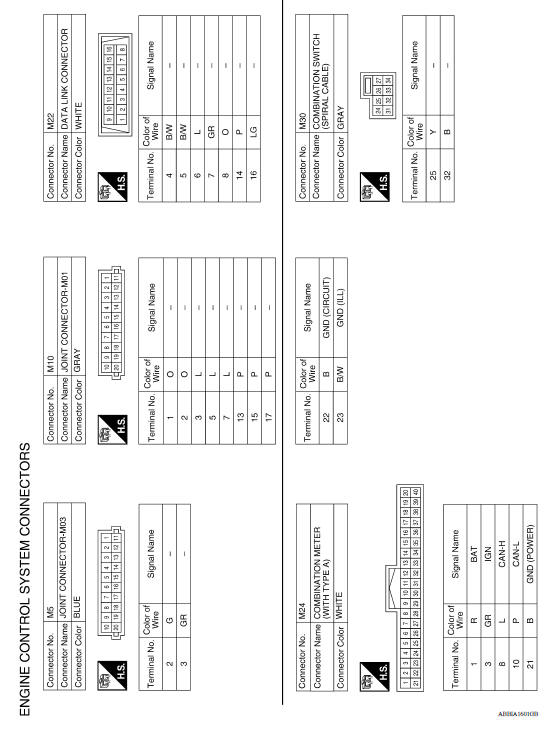
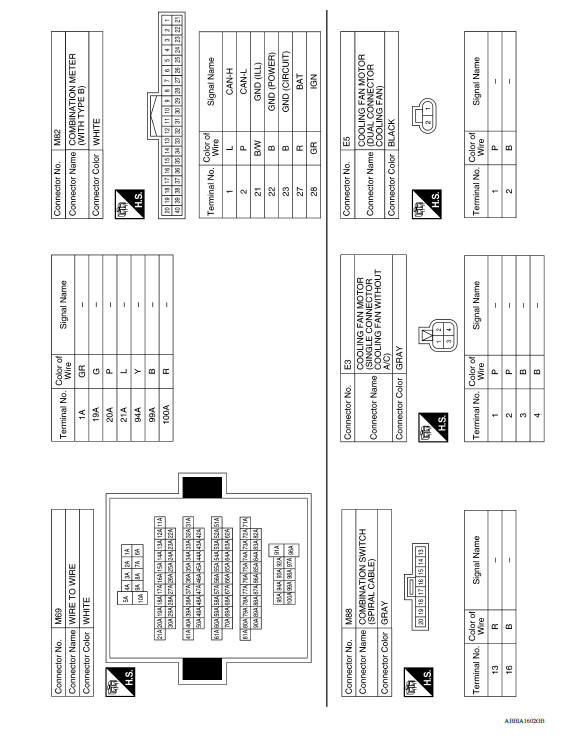
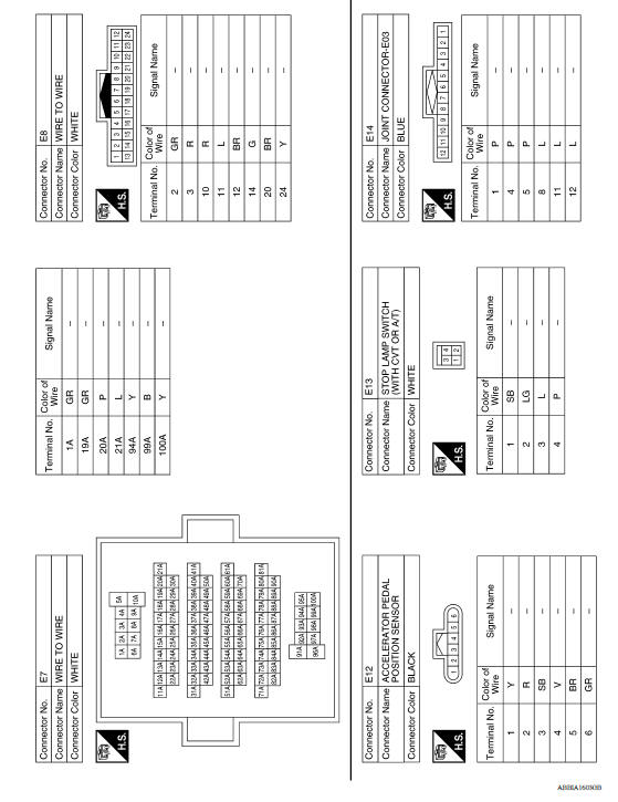
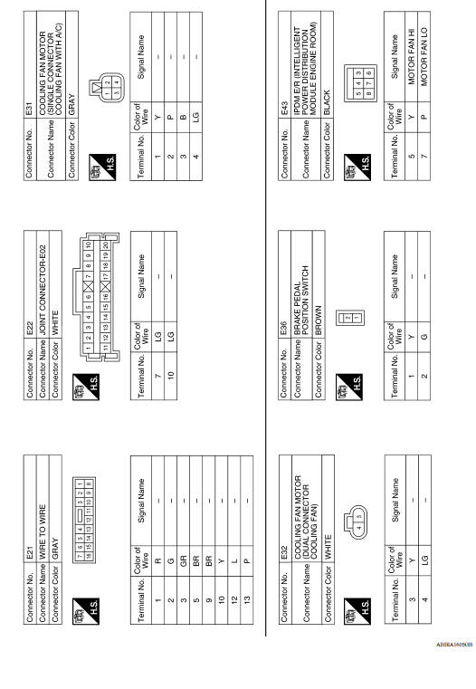
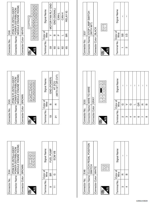
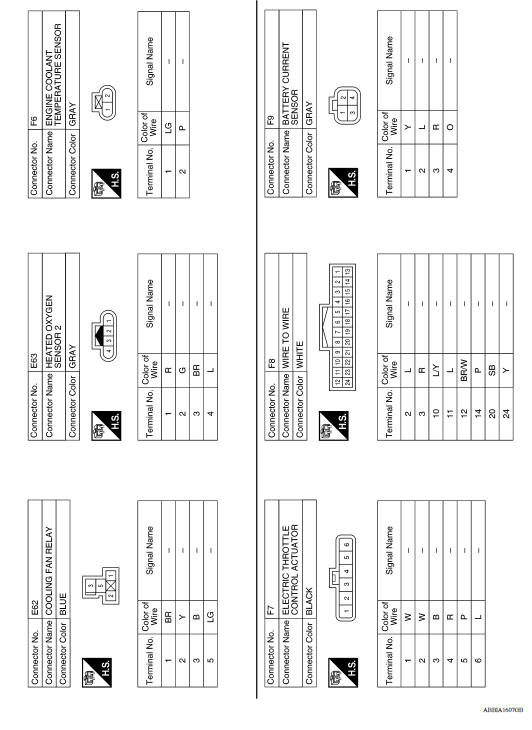
Engine control system
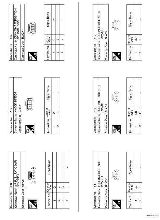
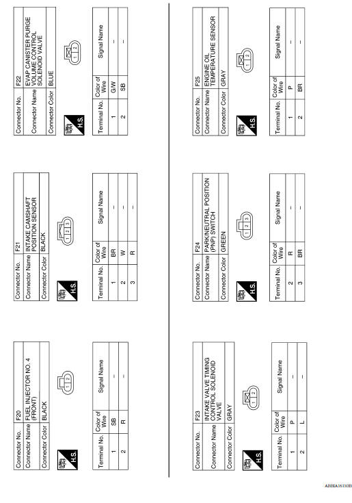
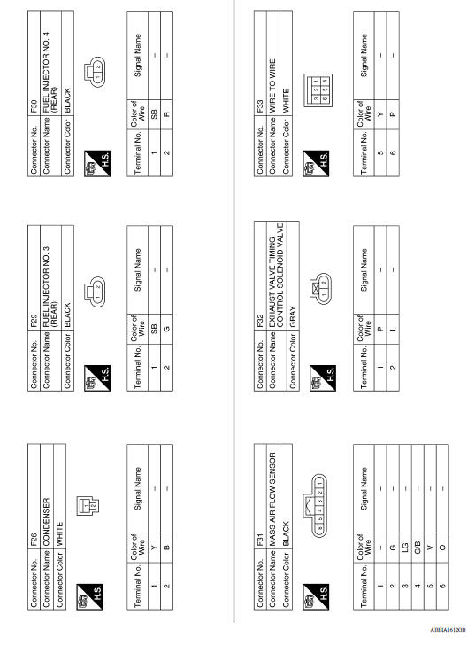
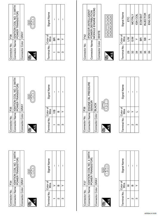
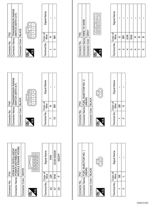
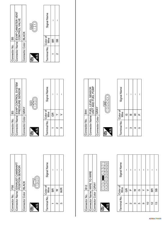
Wiring Diagram
 Diagnosis description
Other materials:
EVAP canister filter
Exploded View
1. EVAP canister vent control valve hose 2. Canister drain hose 3. EVAP
canister filter
Front
Removal and Installation
REMOVAL
Remove the EVAP canister protector cover.
Disconnect EVAP canister vent control valve hose from EVAP canister
filter.
Disconnect caniste ...
Position switch
Removal and Installation
REMOVAL
Drain gear oil. Refer to TM, "Draining".
Disconnect the harness connector (A) from position switch.
Remove position switch from transaxle case.
INSTALLATION
Apply recommended sealant to threads of position switch.
&nbs ...
Categories
- Manuals Home
- Nissan Versa Owners Manual
- Nissan Versa Service Manual
- Video Guides
- Questions & Answers
- External Resources
- Latest Updates
- Most Popular
- Sitemap
- Search the site
- Privacy Policy
- Contact Us

0.006