Nissan Versa (N17): Electrical load signal
Description
The electrical load signal (Headlamp switch signal, rear window defogger switch signal, etc.) is transferred to ECM through the CAN communication line.
Component Function Check
1.CHECK REAR WINDOW DEFOGGER SWITCH FUNCTION
- Turn ignition switch ON.
- Select "DATA MONITOR" mode with CONSULT.
- Select "LOAD SIGNAL" and check indication under the following
conditions.
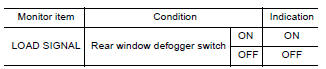
Is the inspection result normal?
YES >> GO TO 2.
NO >> Go to EC, "Diagnosis Procedure".
2.CHECK LIGHTING SWITCH FUNCTION
Check "LOAD SIGNAL" indication under the following conditions.
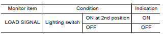
Is the inspection result normal?
YES >> GO TO 3.
NO >> Go to EC, "Diagnosis Procedure".
3.CHECK HEATER FAN CONTROL SWITCH FUNCTION
Select "HEATER FAN SW" and check indication under the following conditions
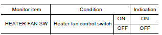
Is the inspection result normal?
YES >> INSPECTION END
NO >> Go to EC, "Diagnosis Procedure".
Diagnosis Procedure
1.INSPECTION START
Confirm the malfunctioning circuit (rear window defogger, headlamp or heater fan). Refer to EC, "Component Function Check".
Which circuit is related to the incident?
Rear window defogger>>GO TO 2
Headlamp>>GO TO 3.
Heater fan>>GO TO 4.
2.CHECK REAR WINDOW DEFOGGER SYSTEM
Perform trouble diagnosis of rear window defogger system. Refer to DEF, "Work Flow".
>> INSPECTION END
3.CHECK HEADLAMP SYSTEM
Perform trouble diagnosis of headlamp system. Refer to EXL, "Work Flow".
>> INSPECTION END
4.CHECK AIR CONDITIONING SYSTEM
Perform trouble diagnosis of air conditioning system. Refer to HA, "Workflow".
>> INSPECTION END
 Cooling fan
Other materials:
A/T Shift lock system
A/T Shift lock system : component parts
location
1 Stop lamp switch. 2 Shift lock release lever. 3 Park position switch.
4 Shift lock solenoid.
A/T Shift lock system : component description
...
Unbalance steering wheel turning force (torque variation)
Description
Unbalance steering wheel turning force (torque variation).
Diagnosis Procedure
1.PERFORM SELF-DIAGNOSIS
With CONSULT
Turn the ignition switch OFF to ON.
Perform "EPS" self-diagnosis.
Is any DTC detected?
YES >> Check the DTC. Refer to STC "DTC Index".
NO & ...
Categories
- Manuals Home
- Nissan Versa Owners Manual
- Nissan Versa Service Manual
- Video Guides
- Questions & Answers
- External Resources
- Latest Updates
- Most Popular
- Sitemap
- Search the site
- Privacy Policy
- Contact Us

0.0053