Nissan Versa (N17): EPS Branch line circuit
Diagnosis Procedure
1.CHECK CONNECTOR
1. Turn the ignition switch OFF.
2. Disconnect the battery cable from the negative terminal.
3. Check the terminals and connectors of the EPS control unit for damage, bend and loose connection (unit side and connector side).
Is the inspection result normal?
YES >> GO TO 2.
NO >> Repair the terminal and connector.
2.CHECK HARNESS FOR OPEN CIRCUIT
1. Disconnect the connector of EPS control unit.
2. Check the resistance between the EPS control unit harness connector
terminals.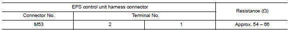
Is the measurement value within the specification?
YES >> GO TO 3.
NO >> Repair the EPS control unit branch line.
3.CHECK POWER SUPPLY AND GROUND CIRCUIT
Check the power supply and the ground circuit of the EPS control unit. Refer to STC "Diagnosis Procedure".
Is the inspection result normal?
YES (Present error)>>Replace the EPS control unit. Refer to STC "Removal and Installation".
YES (Past error)>>Error was detected in the EPS control unit branch line.
NO >> Repair the power supply and the ground circuit.
 DLC Branch line circuit
Diagnosis Procedure 1.CHECK CONNECTOR 1. Turn the ignition switch OFF. 2. Disconnect the battery cable from the negative terminal. 3. Check the terminals and connectors of the data link connector ...
M&A Branch line circuit
Diagnosis Procedure 1.CHECK CONNECTOR 1. Turn the ignition switch OFF. 2. Disconnect the battery cable from the negative terminal. 3. Check the terminals and connectors of the combination meter ...
Other materials:
Electric ignition system
ELECTRIC IGNITION SYSTEM : System Diagram
ELECTRIC IGNITION SYSTEM : System Description
INPUT/OUTPUT SIGNAL CHART
Sensor
Input signal to ECM
ECM function
Actuator
Crankshaft position sensor (POS)
Engine speed*3
Piston position
Ignition timing control
Igni ...
Component inspection
Inspection
AFTER A COLLISION
WARNING:
Inspect all seat belt assemblies including retractors and attaching hardware
after any collision.
NISSAN/INFINITI recommends that all seat belt assemblies in use during a
collision be replaced
unless the collision was minor and the belts show no dam ...
Categories
- Manuals Home
- Nissan Versa Owners Manual
- Nissan Versa Service Manual
- Video Guides
- Questions & Answers
- External Resources
- Latest Updates
- Most Popular
- Sitemap
- Search the site
- Privacy Policy
- Contact Us

0.0046