Nissan Versa (N17): BCM
Reference Value
NOTE: The Signal Tech II Tool (J-50190) can be used to perform the following functions. Refer to the Signal Tech II User Guide for additional information.
- Activate and display TPMS transmitter IDs
- Display tire pressure reported by the TPMS transmitter
- Read TPMS DTCs
- Register TPMS transmitter IDs
- Test remote keyless entry keyfob relative signal strength
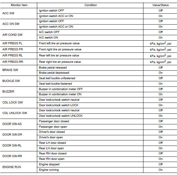
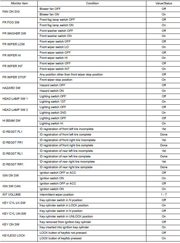
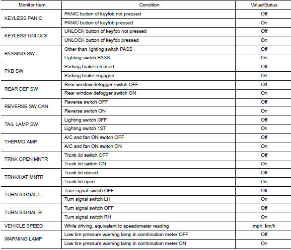
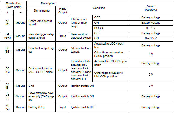
VALUES ON THE DIAGNOSIS TOOL
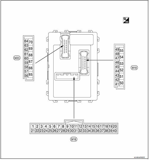
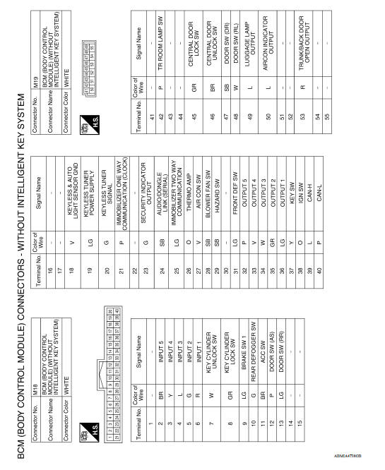
TERMINAL LAYOUT
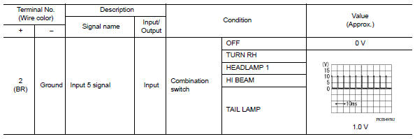
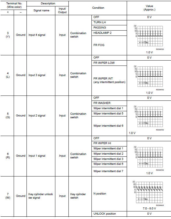
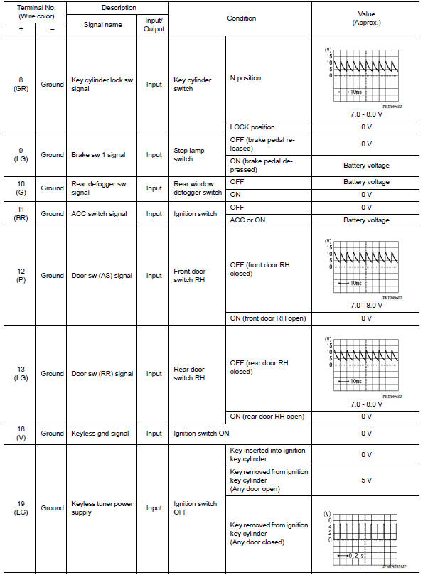
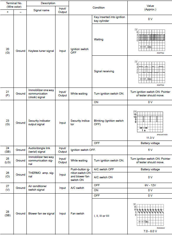
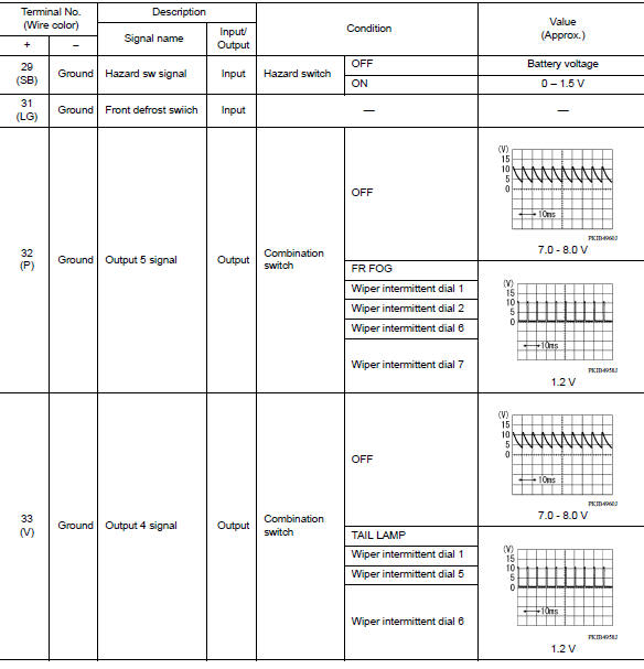
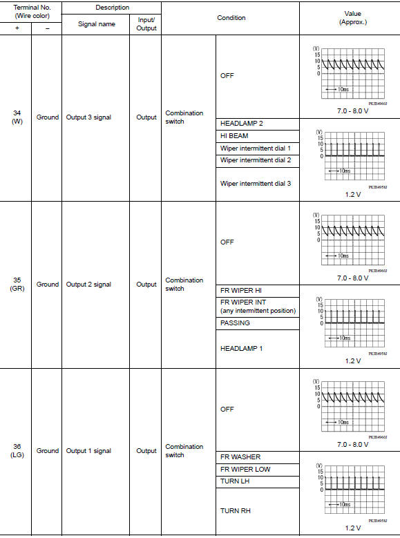
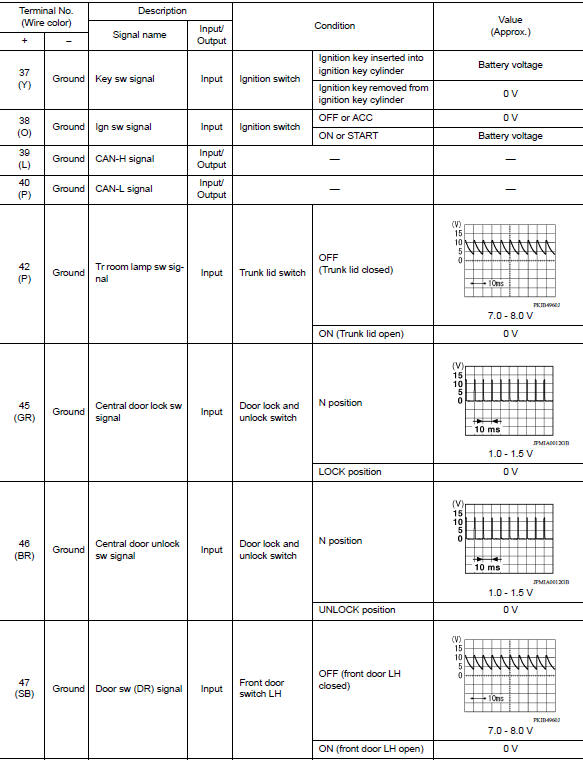
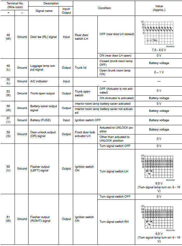
PHYSICAL VALUES
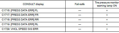
Fail-safe
FAIL-SAFE CONTROL BY DTC
BCM performs fail-safe control when any DTC are detected.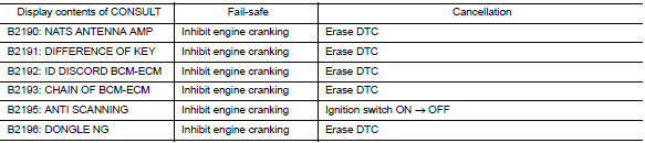
FAIL-SAFE CONTROL OF COMBINATION SWITCH READING FUNCTION CAUSED BY LOW POWER SUPPLY VOLTAGE
If voltage of battery power supply lower, BCM maintains combination switch reading to the status when input voltage is less than approximately 9 V.
NOTE: When voltage of battery power supply is approximately 9 V or more, combination switch reading function returns to normal operation.
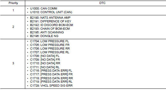
DTC Inspection Priority Chart
If some DTCs are displayed at the same time, perform inspections one by one based on the following priority chart.
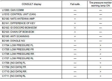
DTC Index
NOTE: Details of time display
- CRNT: Displays when there is a malfunction now or after returning to the normal condition until turning ignition switch OFF → ON again.
- 1 - 39: Displayed if any previous malfunction is present when current condition is normal. It increases like 1 → 2 → 3...38 → 39 after returning to the normal condition whenever ignition switch OFF → ON. The counter remains at 39 even if the number of cycles exceeds it. It is counted from 1 again when turning ignition switch OFF → ON after returning to the normal condition if the malfunction is detected again.
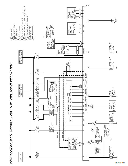
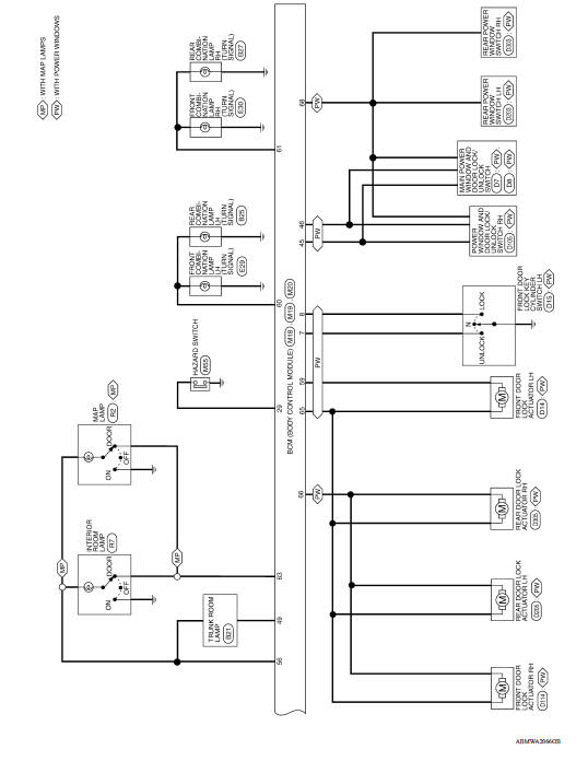
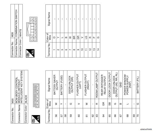
WIRING DIAGRAM
BCM
Wiring Diagram
BASIC INSPECTION
 System
Other materials:
Jump starting
To start your engine with a booster battery, the
instructions and precautions below must be followed.
WARNING
If done incorrectly, jump starting can
lead to a battery explosion, resulting in
severe injury or death. It could also
damage your vehicle.
Explosive hydrogen gas is always pre ...
Shift position indicator circuit
Component Parts Function Inspection
1.CHECK SHIFT POSITION INDICATOR
Start the engine.
Shift the selector lever.
Check that the selector lever position and the shift position indicator
on the combination meter are identical.
Is the inspection result normal?
YES >> INSPECTION ...
Categories
- Manuals Home
- Nissan Versa Owners Manual
- Nissan Versa Service Manual
- Video Guides
- Questions & Answers
- External Resources
- Latest Updates
- Most Popular
- Sitemap
- Search the site
- Privacy Policy
- Contact Us

0.0078