Nissan Versa (N17): Front door speaker
Diagnosis Procedure
Regarding Wiring Diagram information, refer to AV "Wiring Diagram".
1.CONNECTOR CHECK
Check the AV control unit and speaker connectors for the following:
- Proper connection
- Damage
- Disconnected or loose terminals
Is the inspection result normal?
YES >> GO TO 2
NO >> Repair the terminals or connectors.
2.CHECK FRONT DOOR SPEAKER SIGNAL CIRCUIT CONTINUITY
1. Disconnect AV control unit connector M70 and suspect front door speaker connector.
2. Check continuity between AV control unit connector M70 and suspect front
door speaker connector.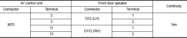
3. Check continuity between AV control unit connector M70 and ground.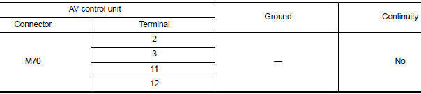
Is the inspection result normal?
YES >> GO TO 3
NO >> Repair or replace harness or connectors.
3.CHECK FRONT DOOR SPEAKER SIGNAL
1. Connect AV control unit connector M70 and suspect front door speaker connector.
2. Turn ignition switch to ACC.
3. Push AV control unit POWER switch.
4. Check signal between the terminals of AV control unit connector M70.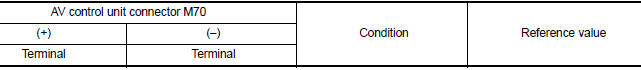
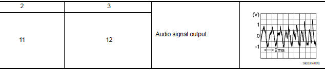
Is the inspection result normal?
YES >> Replace front door speaker. Refer to AV "Removal and Installation".
NO >> Replace AV control unit. Refer to AV "Removal and Installation".
 Power supply and ground circuit
AV CONTROL UNIT AV CONTROL UNIT : Diagnosis Procedure Regarding Wiring Diagram information, refer to AV "Wiring Diagram". 1.CHECK FUSE Check that the following fuses are not blown. Are ...
Rear door speaker
Diagnosis Procedure Regarding Wiring Diagram information, refer to AV "Wiring Diagram". 1.CONNECTOR CHECK Check the AV control unit and speaker connectors for the following: Proper ...
Other materials:
Cleaning interior
Occasionally remove loose dust from the interior
trim, plastic parts and seats using a vacuum
cleaner or soft bristled brush. Wipe the vinyl and
leather surfaces with a clean, soft cloth dampened
in mild soap solution, then wipe clean with a
dry, soft cloth.
Regular care and cleaning is requ ...
Additional service when replacing
ECM
Description
When replacing ECM, the following procedure must be performed.
PROGRAMMING OPERATION
NOTE:
After replacing with a blank ECM, programming is required to write ECM
information. Be sure to follow the procedure
to perform the programming.
Work Procedure
1.CHECK ECM PART NUMBER
Che ...
Categories
- Manuals Home
- Nissan Versa Owners Manual
- Nissan Versa Service Manual
- Video Guides
- Questions & Answers
- External Resources
- Latest Updates
- Most Popular
- Sitemap
- Search the site
- Privacy Policy
- Contact Us

0.0047