Nissan Versa (N17): Power supply and ground circuit
AV CONTROL UNIT
AV CONTROL UNIT : Diagnosis Procedure
Regarding Wiring Diagram information, refer to AV "Wiring Diagram".
1.CHECK FUSE
Check that the following fuses are not blown.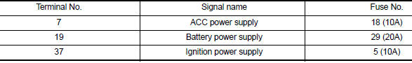
Are the fuses blown?
YES >> Replace the blown fuse after repairing the affected circuit.
NO >> GO TO 2.
2.CHECK POWER SUPPLY CIRCUIT
1. Turn ignition switch OFF.
2. Disconnect AV control unit connectors M70 and M71.
3. Check voltage between AV control unit connectors M70 and M71 and ground.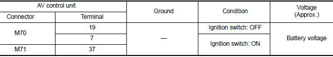
Is the inspection result normal?
YES >> GO TO 3.
NO >> Repair or replace harness or connectors.
3.CHECK GROUND CIRCUIT
1. Turn ignition switch OFF.
2. Check continuity between AV control unit connector M70 and ground.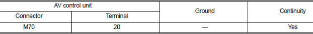
Is the inspection result normal?
YES >> Inspection End.
NO >> Repair or replace harness or connectors.
 U12B1 Power supply voltage
DTC Logic DTC DETECTION LOGIC Diagnosis Procedure 1.CHECK CHARGING SYSTEM Check the vehicle charging system. Refer to CHG "Work Flow (With EXP-800 NI or GR8-1200 NI)" or CHG "W ...
Front door speaker
Diagnosis Procedure Regarding Wiring Diagram information, refer to AV "Wiring Diagram". 1.CONNECTOR CHECK Check the AV control unit and speaker connectors for the following: Proper co ...
Other materials:
Brakes
If the brakes do not operate properly, have the
brakes checked. It is recommended that you visit
a NISSAN dealer for this service.
Self-adjusting brakes
Your vehicle is equipped with self-adjusting
brakes.
The front disc-type brakes self-adjust every time
the brake pedal is applied. The rea ...
Disc rotor
DISC ROTOR : Inspection and Adjustment
INSPECTION
Appearance
Check surface of disc rotor for uneven wear, cracks, and serious damage.
Replace it if necessary. Refer to
BR "DISC ROTOR : Inspection and Adjustment".
Runout
Fix the disc rotor to the wheel hub and bearing assembly wi ...
Categories
- Manuals Home
- Nissan Versa Owners Manual
- Nissan Versa Service Manual
- Video Guides
- Questions & Answers
- External Resources
- Latest Updates
- Most Popular
- Sitemap
- Search the site
- Privacy Policy
- Contact Us

0.0058