Nissan Versa (N17): Front fender
FRONT FENDER : Removal and Installation
CAUTION: Use a shop cloths to protect the body from being damaged during removal and installation.
REMOVAL
- Remove fender protector. Refer to EXT "Removal and Installation".
- Remove front bumper fascia and bumper side bracket. Refer to EXT "Removal and Installation".
- Remove front combination lamp. Refer to EXL "Removal and Installation".
- Remove front door corner finisher. Refer to INT "Removal and Installation".
- Remove front fender cover. Refer to DLK "FENDER COVER : Removal and Installation".
- Remove front fender bolts from front fender.
- Remove front fender stiffener (2) while carefully pulling upper portion of front fender (1) away from body.
 : Front
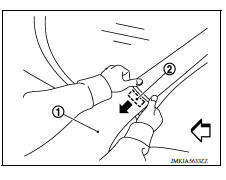
8. Remove front fender.
CAUTION: A viscous urethane foam is installed on the back surface of front fender. When removing the front fender, be careful to not deform the front fender while performing the procedure and removing the viscous urethane foam a little at a time.
INSTALLATION
Installation is in the reverse order of removal.
CAUTION:
- Adjust the following components as necessary.
- Hood assembly: Refer to DLK "HOOD ASSEMBLY : Adjustment".
- Front door assembly: Refer to DLK "DOOR ASSEMBLY : Adjustment".
- After adjusting, apply touch-up paint (body color) onto the head of the front fender bolts.
 Radiator core support lower
RADIATOR CORE SUPPORT LOWER : Removal and Installation RADIATOR CORE SUPPORT LOWER Removal 1. Remove under cover. Refer to EXT "Removal and Installation". 2. Remove radiator upper sea ...
Fender cover
FENDER COVER : Removal and Installation REMOVAL 1. Fully open hood assembly. 2. Disengage pawls beginning at the front of the fender cover and working toward the rear of vehicle and then remove fr ...
Other materials:
Starting the engine (models with NISSAN Intelligent Key system)
1. Apply the parking brake.
2. Move the shift lever to P (Park) or N (Neutral).
P (Park) is recommended.
The starter is designed not to operate if
the shift lever is in any of the driving
positions.
3. Push the ignition switch to the ON position.
Depress the brake pedal and push the ...
Stall test
Work Procedure
INSPECTION
Inspect the amount of engine oil. Replenish the engine oil if necessary.
Refer to LU "Inspection".
Drive for about 10 minutes to warm up the vehicle so that the A/T fluid
temperature is 50 to 80C (122 to
176F).
Inspect the amount of ATF. Replenish ...
Categories
- Manuals Home
- Nissan Versa Owners Manual
- Nissan Versa Service Manual
- Video Guides
- Questions & Answers
- External Resources
- Latest Updates
- Most Popular
- Sitemap
- Search the site
- Privacy Policy
- Contact Us

0.005