Nissan Versa (N17): Front fog lamp aiming adjustment
Inspection
PREPARATION BEFORE ADJUSTING
CAUTION: Do not use organic solvent (thinner, gasoline etc.)
NOTE:
- For details, refer to the regulations in your own country.
- Perform aiming if the vehicle front body has been repaired and/or the front fog lamp has been replaced.
- Before performing aiming adjustment, check the following.
- Keep all tires inflated to correct pressure.
- Place vehicle on level ground.
- See that vehicle is unloaded (except for full levels of coolant, engine oil and fuel, and spare tire, jack, and tools). Have the driver or equivalent weight placed in driver seat.
- Adjust aiming in the vertical direction by turning the adjusting screw.
- When performing adjustment, if necessary, cover the headlamps and opposite fog lamp.
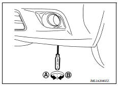
AIMING ADJUSTMENT SCREW
- Turn the aiming adjusting screw using a suitable tool to aim the fog lamp.
A: UP
B: DOWN
- For the position and direction of the adjusting screw refer to the figure as shown.
Aiming Adjustment Procedure
1. Screen placement.
NOTE:
- Place the screen perpendicular to the level road.
- Position the vehicle facing the screen with 10 m (32.8 ft) between the front fog lamp center and the screen.
2. Start the engine. Illuminate the front fog lamp.
CAUTION: Do not cover the lens surface with a tape etc. The lens are made of resin.
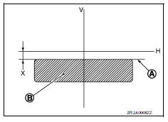
3. Adjust the cutoff line height (A) with the aiming adjustment screw so that the distance (X) between the horizontal center line of front fog lamp (H) and (A) becomes 200 mm (7.87 in).
Front fog lamp light distribution on the screen
- A :Cutoff line
- B :High illuminance
- H :Horizontal center line of front fog lamp
- V :Vertical center line of front fog lamp
- X :Cutoff line height
REMOVAL AND INSTALLATION
 Headlamp aiming adjustment
Front combination lamp
Exploded View 1. Front combination lamp (LH) ...
Other materials:
Lock-up control
LOCK-UP CONTROL : System Description
SYSTEM DIAGRAM
DESCRIPTION
Controls for improvement of the transmission efficiency by engaging the
torque converter clutch in the
torque converter and eliminating slip of the converter. Achieves comfortable
driving with slip control of the
t ...
Keyfob ID set up without consult
ID Code Entry Procedure
KEYFOB ID SET UP WITHOUT CONSULT
NOTE:
If a keyfob is lost, the ID code of the lost keyfob must be erased to
prevent unauthorized use. A specific ID
code can be erased with CONSULT. However, when the ID code of a lost keyfob
is not known, all controller ID c ...
Categories
- Manuals Home
- Nissan Versa Owners Manual
- Nissan Versa Service Manual
- Video Guides
- Questions & Answers
- External Resources
- Latest Updates
- Most Popular
- Sitemap
- Search the site
- Privacy Policy
- Contact Us

0.0104