Nissan Versa (N17): Front fog lamp system
FRONT FOG LAMP SYSTEM : System Diagram
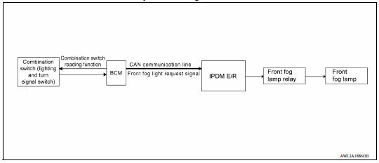
FRONT FOG LAMP SYSTEM : System Description
FRONT FOG LAMP OPERATION
When the combination switch (lighting and turn signal switch) is in front fog lamp ON position and also in 1ST or 2ND position (headlamp is ON), the BCM detects FR FOG ON and the HEAD LAMP 1 or 2 ON. The BCM sends a front fog lamp request ON signal through the CAN communication lines to the IPDM E/R. The IPDM E/R then turns ON the front fog lamp relay sending power to the front fog lamps.
 With daytime light system
WITH DAYTIME LIGHT SYSTEM : System Diagram WITH DAYTIME LIGHT SYSTEM : System Description The headlamp system is equipped with a daytime light relay 1 that activates the high beam headlamps at ...
Turn signal and hazard warning lamp
system
TURN SIGNAL AND HAZARD WARNING LAMP SYSTEM : System Diagram TURN SIGNAL AND HAZARD WARNING LAMP SYSTEM : System Description TURN SIGNAL OPERATION When the turn signal switch is in LH or RH pos ...
Other materials:
Precautions
Precaution for Supplemental Restraint System
(SRS) "AIR BAG" and "SEAT BELT PRE-TENSIONER"
The Supplemental Restraint System such as "AIR BAG" and "SEAT BELT PRE-TENSIONER",
used along
with a front seat belt, helps to reduce the risk or severity of injury to the
driver and ...
Component parts
CVT CONTROL SYSTEM
CVT CONTROL SYSTEM : Component Parts Location
1. IPDM E/R 2. TCM 3. Transmission range switch
4. Primary speed sensor 5. CVT unit 6. Output speed sensor
7. Secondary speed sensor 8. G sensor 9. Stop lamp switch
10. CVT shift selector 11. Overdrive control switch 12. Combi ...
Categories
- Manuals Home
- Nissan Versa Owners Manual
- Nissan Versa Service Manual
- Video Guides
- Questions & Answers
- External Resources
- Latest Updates
- Most Popular
- Sitemap
- Search the site
- Privacy Policy
- Contact Us

0.0048