Nissan Versa (N17): Turn signal and hazard warning lamp system
TURN SIGNAL AND HAZARD WARNING LAMP SYSTEM : System Diagram
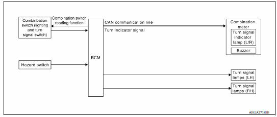
TURN SIGNAL AND HAZARD WARNING LAMP SYSTEM : System Description
TURN SIGNAL OPERATION
When the turn signal switch is in LH or RH position with the ignition switch in ON position, the BCM detects the TURN RH or TURN LH ON request. The BCM outputs the flasher output signal to the respective turn signal lamp. The BCM sends a turn indicator signal ON request through the CAN communication lines to the combination meter. The combination meter then activates the appropriate turn signal indicator and audible buzzer.
HAZARD LAMP OPERATION
When the hazard switch is in ON position, the BCM detects the hazard switch signal ON. The BCM outputs the flasher output signal (right and left). The BCM sends a hazard indicator signal ON request through the CAN communication lines to the combination meter. The combination meter then activates the hazard indicator and audible buzzer.
REMOTE KEYLESS ENTRY OPERATION
The remote keyless entry receiver transmits hazard lamp signal to BCM, then BCM controls hazard lamps.
Refer to DLK "REMOTE KEYLESS ENTRY SYSTEM : System Description".
 Front fog lamp system
FRONT FOG LAMP SYSTEM : System Diagram FRONT FOG LAMP SYSTEM : System Description FRONT FOG LAMP OPERATION When the combination switch (lighting and turn signal switch) is in front fog lamp O ...
Parking, license plate and tail lamp
system
PARKING, LICENSE PLATE AND TAIL LAMP SYSTEM : System Diagram PARKING, LICENSE PLATE AND TAIL LAMP SYSTEM : System Description PARKING, LICENSE PLATE AND TAIL LAMPS OPERATION When the combina ...
Other materials:
Trunk open function
TRUNK OPEN FUNCTION : System Description
System Diagram
TRUNK LID OPENER OPERATION
When the BCM detects that trunk lid opener switch is pressed, it starts
the outside key antenna (rear
bumper) and inside key antenna and transmits the request signal to the
Intelligent Key. Then, c ...
B2098 Ignition relay on stuck
Description
The ignition relay integrated in IPDM E/R is operated with ignition switch ON
signal from the ignition switch.
DTC Logic
DTC DETECTION LOGIC
Diagnosis Procedure
1. PERFORM SELF DIAGNOSTIC RESULT
1. Turn the ignition switch ON.
2. Erase "SELF-DIAG RESULTS" of IPDM E/R.
3. Tu ...
Categories
- Manuals Home
- Nissan Versa Owners Manual
- Nissan Versa Service Manual
- Video Guides
- Questions & Answers
- External Resources
- Latest Updates
- Most Popular
- Sitemap
- Search the site
- Privacy Policy
- Contact Us

0.0049