Nissan Versa (N17): With daytime light system
WITH DAYTIME LIGHT SYSTEM : System Diagram
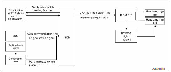
WITH DAYTIME LIGHT SYSTEM : System Description
The headlamp system is equipped with a daytime light relay 1 that activates the high beam headlamps at approximately half illumination whenever the engine is operating and the lighting switch is in the OFF position.
If the parking brake is applied before the engine is started the daytime lights will not be illuminated. The daytime lights will illuminate once the parking brake is released. With the lighting switch in the 2nd position the headlamps function the same as conventional light systems.
The BCM monitors inputs from the parking brake switch and the lighting switch to determine when to activate the daytime light system. The BCM sends a daytime light request to the IPDM E/R via the CAN communication lines.
The IPDM E/R grounds the daytime light relay 1 which in turn, provides power to the ground side of the LH high beam lamp. Power flows backward through the LH high beam lamp to the IPDM E/R, through fuse 35, fuse 34 and to the RH high beam lamp and on to ground. The high beam lamps are wired in series which causes them to illuminate at a reduced intensity.
 Headlamp system
HEADLAMP SYSTEM : System Diagram HEADLAMP SYSTEM : System Description LOW BEAM OPERATION When the lighting switch is in 2nd position, the BCM receives input requesting the headlamps to illu ...
Front fog lamp system
FRONT FOG LAMP SYSTEM : System Diagram FRONT FOG LAMP SYSTEM : System Description FRONT FOG LAMP OPERATION When the combination switch (lighting and turn signal switch) is in front fog lamp O ...
Other materials:
A/T Shift lock system
A/T Shift lock system : component parts
location
1 Stop lamp switch. 2 Shift lock release lever. 3 Park position switch.
4 Shift lock solenoid.
A/T Shift lock system : component description
...
Diagnosis and repair workflow
Workflow
OVERALL SEQUENCE
DETAILED FLOW
1.INTERVIEW CUSTOMER
Interview the customer to obtain as much information as possible about the
conditions and environment under
which the malfunction occurred.
>> GO TO 2.
2.SYMPTOM CHECK
Verify symptoms.
>> GO TO 3.
3.CHECK FOR DT ...
Categories
- Manuals Home
- Nissan Versa Owners Manual
- Nissan Versa Service Manual
- Video Guides
- Questions & Answers
- External Resources
- Latest Updates
- Most Popular
- Sitemap
- Search the site
- Privacy Policy
- Contact Us

0.0045