Nissan Versa (N17): Headlamp system
HEADLAMP SYSTEM : System Diagram
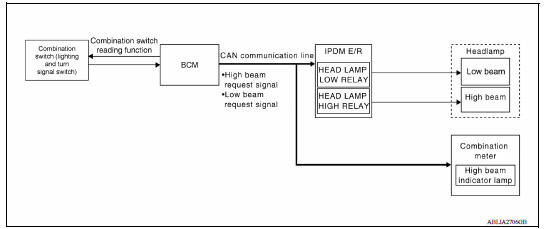
HEADLAMP SYSTEM : System Description
LOW BEAM OPERATION
When the lighting switch is in 2nd position, the BCM receives input requesting the headlamps to illuminate.
This input is communicated to the IPDM E/R across the CAN communication lines. The CPU of the IPDM E/R controls the headlamp low relay coil which supplies power to the low beam headlamps.
HIGH BEAM OPERATION/FLASH-TO-PASS OPERATION
With the lighting switch in the 2nd position and placed in HIGH position, the BCM receives input requesting the headlamp high beams to illuminate. The flash to pass feature can be used any time and also sends a signal to the BCM. This input is communicated to the IPDM E/R across the CAN communication lines. The CPU of the combination meter controls the ON/OFF status off the HIGH BEAM indicator. The CPU of the IPDM E/R controls the headlamp high relay coil which supplies power to the high beam headlamps.
The combination meter receives a high beam request signal (ON) through the CAN communication lines and turns the high beam indicator lamp ON.
EXTERIOR LAMP BATTERY SAVER CONTROL
With the combination switch (lighting and turn signal switch) in the 2nd position and the ignition switch is turned from ON or ACC to OFF, the battery saver feature is activated.
Under this condition, the headlamps remain illuminated for 45 seconds unless the lighting switch position is changed. If the lighting switch position is changed, then the headlamps are turned off.
This setting can be changed by CONSULT. Refer to BCS "HEADLAMP : CONSULT Function (BCM - HEAD LAMP)".
 Precautions
With daytime light system
WITH DAYTIME LIGHT SYSTEM : System Diagram WITH DAYTIME LIGHT SYSTEM : System Description The headlamp system is equipped with a daytime light relay 1 that activates the high beam headlamps at ...
Other materials:
Intake manifold
Exploded View
1. EVAP canister purge volume control
solenoid valve
2. Hose clamp 3. Vacuum hose
4. PCV hose 5. Hose clamp 6. Intake manifold support
7. Gasket 8. Intake manifold 9. Electric throttle control actuator
10. Gasket 11. EVAP service port
A. To air duct B. To centralized underf ...
Malfunction indicator lamp
Component Function Check
1.CHECK MIL FUNCTION
Turn ignition switch ON.
Make sure that MIL lights up.
Is the inspection result normal?
YES >> INSPECTION END
NO >> Go to EC, "Diagnosis Procedure".
Diagnosis Procedure
1.CHECK DTC
Check that DTC UXXXX is not display ...
Categories
- Manuals Home
- Nissan Versa Owners Manual
- Nissan Versa Service Manual
- Video Guides
- Questions & Answers
- External Resources
- Latest Updates
- Most Popular
- Sitemap
- Search the site
- Privacy Policy
- Contact Us

0.0047