Nissan Versa (N17): Front regulator
Exploded View
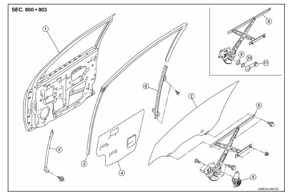
1. Front door panel 2. Front door lower sash (front) 3. Front door glass run 4. Front door sealing screen 5. Front door power window motor 6. Front door regulator 7. Front door glass 8. Front door lower sash (rear) 9. Regulator seal (manual window) 10. Snap pin (manual window) 11. Regulator handle (manual window)
Removal and Installation
REMOVAL
1. Remove front door glass. Refer to GW "Removal and Installation".
2. Disconnect the harness connector from front door power window motor.
3. Remove front door regulator assembly bolts and nuts.
4. Remove front door regulator assembly from front door panel.
INSTALLATION
Installation is in the reverse order of removal.
Disassembly and Assembly
DISASSEMBLY
Remove the power window motor from the regulator assembly.
INSPECTION AFTER REMOVAL
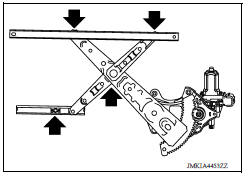
Check the regulator assembly for the following items. Replace or grease it if a malfunction is detected.
- Wire wear
- Regulator deformation
- The arrows shows the application points of the multi-purpose grease.
ASSEMBLY
Assembly is in the reverse order of disassembly.
Inspection and Adjustment
FITTING INSPECTION
- Check that the glass fits securely into the sash groove.
- Lower the glass slightly [approximately 10 to 20 mm (0.394 to 0.787 in)], and check that the clearance to the sash is parallel. Loosen the regulator bolts, guide rail bolts, and glass and guide rail bolts to correct the glass position if the clearance between the glass and sash is not parallel.
 Front door glass
Exploded View 1. Front door panel 2. Front door lower sash (front) 3. Front door glass run 4. Front door sealing screen 5. Front door power window motor 6. Front door regulator 7. Front door ...
Rear door glass
Exploded View 1. Rear door panel 2. Sealing screen 3. Rear door sash 4. Power window motor 5. Regulator assembly 6. Partition sash 7. Partition glass 8. Rear door glass 9. Partition weather-st ...
Other materials:
Brake caliper assembly
BRAKE CALIPER ASSEMBLY : Exploded View
REMOVAL
1. Brake caliper assembly
DISASSEMBLY
1. Cap 2. Bleeder valve 3. Cylinder body
4. Piston seal 5. Piston 6. Piston boot
7. Sliding pin 8. Sliding pin boot 9. Bushing
10. Torque member Apply rubber
grease Apply brake fluid
NOTE:
LH front ...
Rear seat
Exploded View - Fixed Seatback
FIXED SEATBACK
1. Headrest holder (locked) 2. Headrest holder (free) 3. Rear seatback
assembly
4. Seatback trim 5. Seatback pad 6. LATCH bracket (RH)
7. Seat cushion assembly 8. Seat cushion trim 9. Seat cushion pad
10. Seat cushion hook 11. LATCH bracket (L ...
Categories
- Manuals Home
- Nissan Versa Owners Manual
- Nissan Versa Service Manual
- Video Guides
- Questions & Answers
- External Resources
- Latest Updates
- Most Popular
- Sitemap
- Search the site
- Privacy Policy
- Contact Us

0.0047