Nissan Versa (N17): Front door glass
Exploded View
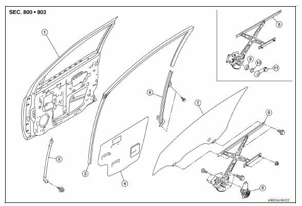
1. Front door panel 2. Front door lower sash (front) 3. Front door glass run 4. Front door sealing screen 5. Front door power window motor 6. Front door regulator 7. Front door glass 8. Front door lower sash (rear) 9. Regulator seal (manual window) 10. Snap pin (manual window) 11. Regulator handle (manual window)
Removal and Installation
REMOVAL
1. Fully open front door glass.
2. Remove front door finisher. Refer to INT "Removal and Installation".
3. Disconnect door mirror harness connector and remove the clip.
4. Remove front door sealing screen.
NOTE: Cut the butyl-tape so that some parts of the butyl-tape will remain on the sealing screen, if the sealing screen is reused.
5. Partially remove front door glass run.
6. Perform the following to access glass bolts.
- Operate the main power window or power window and door lock and unlock motor switch to raise or lower the door window until the glass bolts (A) can be seen.
- Operate the regulator handle to raise or lower the door window until the glass bolts (A) can be seen.
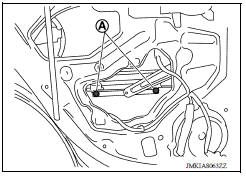
7. Remove the glass bolts.
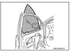
8. Correctly position the front door glass to pull it out of the sash and remove the door glass from the door.
9. Remove front door outside molding. Refer to EXT "Removal and Installation".
10. Remove front door glass run.
11. Remove front door lower sash (rear).
- Remove lower sash (rear) bolts.
- Hold the upper part of lower sash and then pull it up to remove.
12. Remove front door lower sash (front).
- Remove lower sash (front) bolt.
- Hold the upper part of lower sash and then pull it up to remove.
INSTALLATION
Installation is in the reverse order of removal.
Inspection and Adjustment
FITTING INSPECTION
- Make sure that the glass fits securely into the sash groove.
- Lower the glass slightly [approximately 10 to 20 mm (0.394 to 0.787 in)], and check that the clearance to the sash is parallel. Loosen the regulator bolts, guide rail bolts, and glass and guide rail bolts to correct the glass position if the clearance between the glass and sash is not parallel.
 Rear window glass
Exploded View 1. Rear window glass 2. Rear window glass holder (RH) 3. Dam sealant rubber (upper) 4. Rear window glass holder (LH) 5. Dam sealant rubber (lower) 6. Glass primer 7. Adhesive 8 ...
Front regulator
Exploded View 1. Front door panel 2. Front door lower sash (front) 3. Front door glass run 4. Front door sealing screen 5. Front door power window motor 6. Front door regulator 7. Front door ...
Other materials:
Fuel level sensor unit
Disassembly and Assembly
Fuel Level Sender Unit
1. Harness connectors 2. Level sending unit module 3. Fuel temperature sensor
4. Float arm assembly
Disassembly
NOTE:
Before disassembly, note the proper placement of the wires to the correct
terminals and correct wire routing to
the term ...
P062F EEPROM
Description
TCM compares the calculated value stored in the flash ROM with the value
stored in TCM. If the calculated
value does not agree with the stored value, TCM judges this as a malfunction.
DTC Logic
DTC DETECTION LOGIC
DTC
Trouble diagnosis name
DTC detection condition
...
Categories
- Manuals Home
- Nissan Versa Owners Manual
- Nissan Versa Service Manual
- Video Guides
- Questions & Answers
- External Resources
- Latest Updates
- Most Popular
- Sitemap
- Search the site
- Privacy Policy
- Contact Us

0.005