Nissan Versa (N17): G Sensor
Exploded View
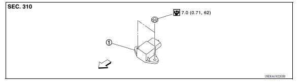
1. G sensor
![]() Front
Front
Removal and Installation
CAUTION:
- Do not drop or strike G sensor, because it may be damaged by impact.
- Do not use a power tool.
REMOVAL
- Disconnect the battery negative terminal. Refer to PG "Removal and Installation".
- Remove center console. Refer to IP "Removal and Installation".
- Disconnect the harness connector from G sensor.
- Remove G sensor.
INSTALLATION
Installation is in the reverse order of removal.
Adjustment
ADJUSTMENT AFTER INSTALLATION
Perform "G SENSOR CALIBRATION". Refer to TM "Description".
 Air breather hose
Removal and Installation REMOVAL Remove air duct (inlet). Refer to EM "Exploded View". Remove air breather hose from transaxle assembly. INSTALLATION Installation is in the reve ...
Oil pan
Exploded View 1. Transaxle assembly 2. Oil pan gasket 3. Magnet 4. Oil pan 5. Overflow tube 6. Drain plug gasket 7. Drain plug 8. Oil pan fitting bolt Removal and Installation REMOVAL R ...
Other materials:
Spark plugs
Replacing spark plugs
Platinum-tipped spark plugs
It is not necessary to replace platinum-tipped A
spark plugs as frequently as conventional type
spark plugs because they last much longer. Follow
the maintenance log shown in the Maintenance
and Schedules section of this manual. Do
not ser ...
Shift lock system
Component Function Check
1.CHECK SHIFT LOCK OPERATION (BRAKE PEDAL RELEASED)
Ignition switch ON.
Attempt to shift selector lever to any position other than "P" position
with brake pedal released.
Can the selector lever be shifted?
YES >> Go to TM "Diagnosis Procedure".
...
Categories
- Manuals Home
- Nissan Versa Owners Manual
- Nissan Versa Service Manual
- Video Guides
- Questions & Answers
- External Resources
- Latest Updates
- Most Popular
- Sitemap
- Search the site
- Privacy Policy
- Contact Us

0.0051