Nissan Versa (N17): Coil spring
Exploded View
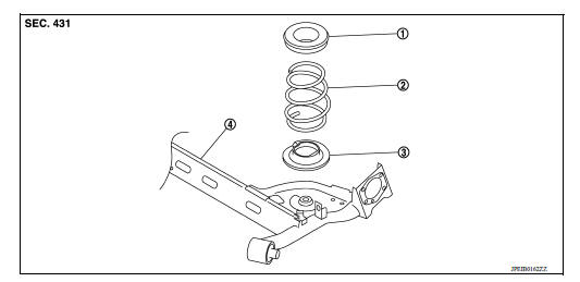
1. Upper rubber seat 2. Coil spring 3. Lower rubber seat 4. Rear suspension beam
Removal and Installation
REMOVAL
- Remove the wheel and tire assemblies using power tool. Refer to WT "Adjustment".
- Position a suitable jack under rear suspension beam.
CAUTION:
- Place the jack in the center of the suspension beam.
- Do not damage the suspension beam with jack.
- Remove the lower shock absorber bolts. Refer to RSU "Removal and Installation".
- Slowly lower jack, then remove upper rubber seat, coil spring and lower rubber seat from rear suspension beam.
INSTALLATION
Installation is in the reverse order of removal.
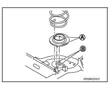
- Install the lower rubber seat (A) to the rear suspension beam mounting hole (B).
- Match up lower rubber seat indentions and rear suspension beam grooves and attach.
Inspection
INSPECTION AFTER REMOVAL
Check rubber seat and coil spring for deformation, crack, and damage. Replace it if necessary.
INSPECTION AFTER INSTALLATION
Check wheel alignment. Refer to RSU "Inspection".
 Rear shock absorber
Exploded View 1. Piston rod lock nut 2. Washer 3. Bushing 4. Distance tube 5. Bound bumper cover 6. Bound bumper 7. Shock absorber assembly 8. Rear suspension beam ...
Rear suspension beam
Exploded View 1. Rear suspension beam Removal and Installation REMOVAL Remove the wheel and tire assemblies using power tool. Refer to WT "Adjustment". Remove wheel sensor ...
Other materials:
Engine control system
ENGINE CONTROL SYSTEM : Component Parts Location
1. Mass air flow sensor
(with intake air temperature sensor)
2. Electric throttle control actuator
(with built in throttle position sensor
and throttle control motor)
3. EVAP canister purge volume control
solenoid valve
4. Cooling fan mot ...
P1148 closed loop control
DTC Logic
DTC DETECTION LOGIC
NOTE:
DTC P1148 is displayed with DTC for A/F sensor 1.
When the DTC is detected, perform the trouble diagnosis of DTC corresponding to
A/F sensor 1.
DTC No.
Trouble diagnosis
(Trouble diagnosis content)
DTC detecting condition
Possible cause ...
Categories
- Manuals Home
- Nissan Versa Owners Manual
- Nissan Versa Service Manual
- Video Guides
- Questions & Answers
- External Resources
- Latest Updates
- Most Popular
- Sitemap
- Search the site
- Privacy Policy
- Contact Us

0.0049