Nissan Versa (N17): Rear suspension beam
Exploded View
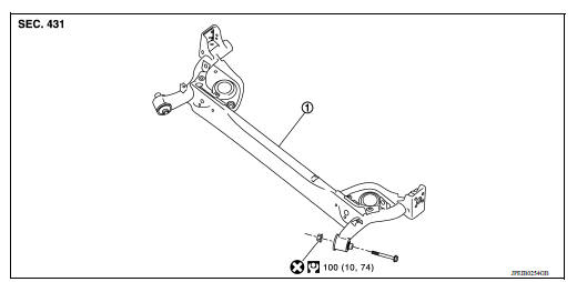
1. Rear suspension beam
Removal and Installation
REMOVAL
- Remove the wheel and tire assemblies using power tool. Refer to WT "Adjustment".
- Remove wheel sensor and sensor harness. Refer to BRC "REAR WHEEL SENSOR : Removal and Installation".
- Remove brake hose and brake pipe from rear suspension beam. Refer to BR "REAR : Removal and Installation".
- Remove the rear drum brake assemblies. Refer to BR "Removal and Installation".
- Remove parking brake cable from rear suspension beam. Refer to PB"Removal and Installation".
- Position a suitable jack under rear suspension beam.
CAUTION:
- Place the jack in the center of the suspension beam.
- Do not damage the suspension beam with jack.
- Remove shock absorber bolts (lower side). Refer to RSU "Removal and Installation".
- Remove coil spring. Refer to RSU "Removal and Installation".
- Remove rear suspension beam bolts and nuts.
- Slowly lower jack, remove rear suspension beam from vehicle body.
CAUTION: While lowering the rear suspension beam with the jack, be sure to maintain the stability of the jack.
INSTALLATION
Installation is in the reverse order of removal.
- Perform final tightening of rear suspension beam installation position (rubber bushing), under unladen conditions with tires on level ground.
- Check wheel sensor harness for proper connection. Refer to BRC "REAR WHEEL SENSOR : Exploded View".
- Adjust parking brake. Refer to PB "Inspection and Adjustment".
- Check wheel alignment. Refer to RSU "Inspection".
SERVICE DATA AND SPECIFICATIONS (SDS)
Wheel Alignment
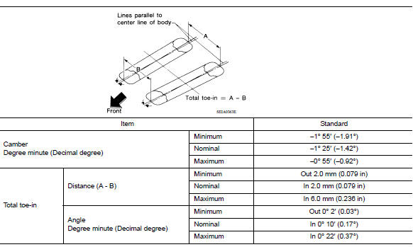
Measure value under unladen* conditions.
*: Fuel, engine coolant and lubricant are full. Spare tire, jack, hand tools and mats are in designated positions.
Wheelarch Height
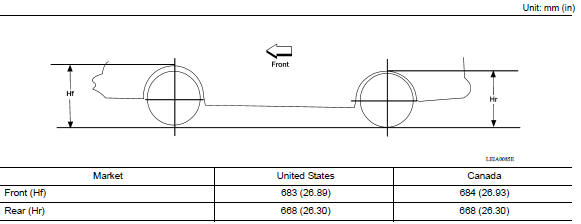
Measure value under unladen* conditions.
*: Fuel, engine coolant and lubricant are full. Spare tire, jack, hand tools and mats are in designated positions.
 Coil spring
Exploded View 1. Upper rubber seat 2. Coil spring 3. Lower rubber seat 4. Rear suspension beam Removal and Installation REMOVAL Remove the wheel and tire assemblies using power tool. Refe ...
PRECAUTIONS
Precaution for Supplemental Restraint System (SRS) "AIR BAG" and "SEAT BELT PRE-TENSIONER" The Supplemental Restraint System such as "AIR BAG" and "SEAT BELT PRE-TENSIONER", us ...
Other materials:
Spark plugs
Replacing spark plugs
Platinum-tipped spark plugs
It is not necessary to replace platinum-tipped A
spark plugs as frequently as conventional type
spark plugs because they last much longer. Follow
the maintenance log shown in the Maintenance
and Schedules section of this manual. Do
not ser ...
Additional service when replacing
TCM
Description
Always perform the following items when the TCM is replaced.
LOADING OF THE CALIBRATION DATA
The TCM acquires calibration data (individual characteristic value) of
each solenoid that is stored in the
ROM assembly (in the control valve). This enables the TCM to perform
accur ...
Categories
- Manuals Home
- Nissan Versa Owners Manual
- Nissan Versa Service Manual
- Video Guides
- Questions & Answers
- External Resources
- Latest Updates
- Most Popular
- Sitemap
- Search the site
- Privacy Policy
- Contact Us

0.0061