Nissan Versa (N17): GPS Antenna
Removal and Installation
REMOVAL
1. Remove the combination meter. Refer to MWI "Removal and Installation" (Type A) or MWI"Removal and Installation" (Type B).
2. Remove the AV control unit. Refer to AV "Removal and Installation".
3. Remove the GPS antenna screw (A), then disconnect the GPS antenna retainer (B).
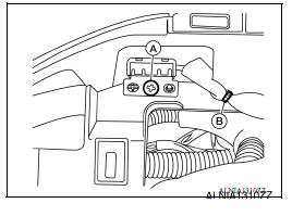
4. Remove the GPS antenna.
INSTALLATION
Installation is in the reverse order of removal.
ANTENNA FEEDER
Feeder Layout
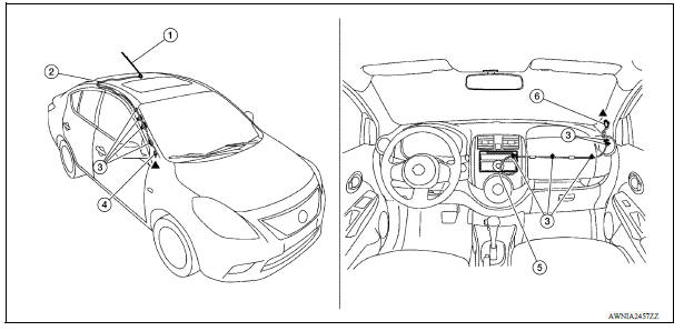
1. Antenna mast 2. Antenna feed 3. Clip 4. Harness connector 5. Audio unit 6. Harness connector
REAR VIEW CAMERA
Removal and Installation
REMOVAL
1. Remove trunk lid finisher. Refer to EXT "Exploded View".
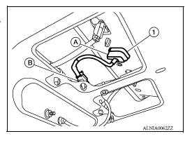
2. Disconnect the harness connector (B) from rear view camera.
3. Press the rear view camera tab (A) and remove the rear view camera (1).
INSTALLATION
Installation is in the reverse order of removal.
 Steering audio control switch
Removal and Installation 1. Steering wheel 2. Steering wheel audio control switches 3. Driver air bag module 4. Steering wheel rear finisher REMOVAL 1. Remove the steering wheel. Refer to ST ...
Precautions
Precaution for Supplemental Restraint System (SRS) "AIR BAG" and "SEAT BELT PRE-TENSIONER" The Supplemental Restraint System such as "AIR BAG" and "SEAT BELT PRE-TENSIONER", us ...
Other materials:
P0705 Transmission range switch A
DTC Logic
DTC DETECTION LOGIC
DTC
Trouble diagnosis name
DTC detection condition
Possible causes
P0705
Transmission Range Sensor
"A" Circuit Malfunction (PRNDL
input)
The following diagnosis conditions
are met and 2 or more position
signals are ON at the
...
Low tire pressure warning lamp
does not turn off
Diagnosis Procedure
1.INSPECT BCM CONNECTOR
Turn ignition switch OFF.
Disconnect BCM connectors.
Check terminals for damage or loose connections.
Is the inspection result normal?
YES >> GO TO 2.
NO >> Repair or replace damaged parts.
2.BCM POWER SUPPLY AND GROUND CIRCUITS ...
Categories
- Manuals Home
- Nissan Versa Owners Manual
- Nissan Versa Service Manual
- Video Guides
- Questions & Answers
- External Resources
- Latest Updates
- Most Popular
- Sitemap
- Search the site
- Privacy Policy
- Contact Us

0.0052