Nissan Versa (N17): Horn
Exploded View
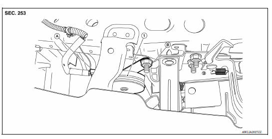
1. Horn A. Connector(s) B. Nut
Removal and Installation
REMOVAL
1. Disconnect the harness connectors from the horn.
2. Remove the horn nut and the horn.
INSTALLATION
Installation is in the reverse order of removal.
 Precautions
Precaution for Supplemental Restraint System (SRS) "AIR BAG" and "SEAT BELT PRE-TENSIONER" The Supplemental Restraint System such as "AIR BAG" and "SEAT BELT PRE-TENSIONER", us ...

Other materials:
Instrument panel
1. Headlight/turn signal switch/fog light
switch (if so equipped)
2. Driver's supplemental air bag (P. 1-39)
Horn
3. Meters and gauges. Warning and indicator lights
4. Wiper and washer switch
5. Vents
6. Rear window defroster switch
7. Front passenger air bag status light
8. Hazard warn ...
Explanation of scheduled maintenance items
The following descriptions are provided to give
you a better understanding of the scheduled
maintenance items that should be regularly
checked or replaced. The maintenance schedule
indicates at which mileage/time intervals each
item requires service.
In addition to scheduled maintenance, you ...
Categories
- Manuals Home
- Nissan Versa Owners Manual
- Nissan Versa Service Manual
- Video Guides
- Questions & Answers
- External Resources
- Latest Updates
- Most Popular
- Sitemap
- Search the site
- Privacy Policy
- Contact Us

0.0049