Nissan Versa (N17): Idle neutral control
IDLE NEUTRAL CONTROL : System Description
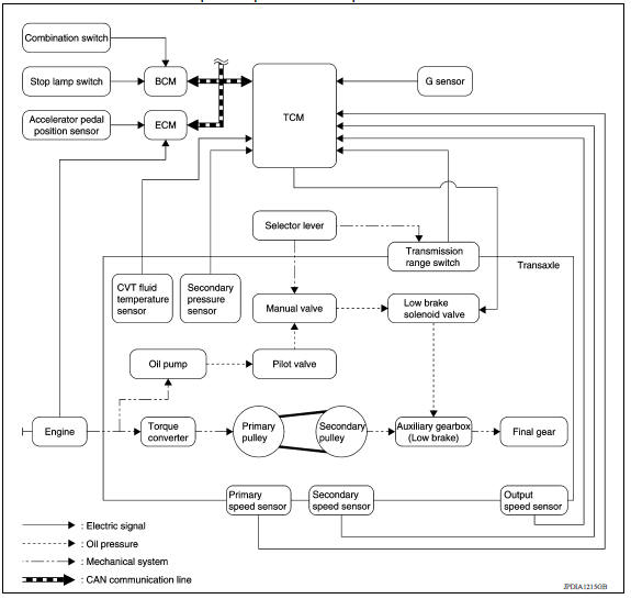
SYSTEM DIAGRAM
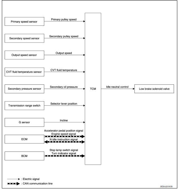
DESCRIPTION
If a driver has no intention of starting the vehicle in D position, TCM operates the low brake solenoid valve and controls the oil pressure of the low brake to be low pressure. Therefore, the low brake is in the release (slip) status and the power transmission route of transaxle is the same status as the N position. In this way, the transaxle is in idling status and load to the engine can be reduced to improve fuel economy.
NOTE: Provides idle neutral control when stop/start operation is not performed.
Idle Neutral Control Start Condition
Idle neutral control is started when all of the following conditions are fulfilled. However, during idle neutral control, idle neutral control is stopped when any of the following conditions is not met or idle neutral control continues 30 seconds.
Driving environment : Flat road or road with mild gradient
Selector lever position : "D" position
Vehicle speed : 0 km/h (0 MPH)
Accelerator pedal position : 0.0/8
Brake pedal : Depressed
Engine speed : Idle speed
Turn signal lamp/hazard signal lamp : Not activated
NOTE: Stops or prohibits the idle neutral control when the TCM and ECM detect that the vehicle is in one of the following conditions.
- Engine coolant temperature and CVT fluid temperature are the specified temperature or more, or the specified temperature or less.
- When a transaxle malfunction occurs.
- When the vehicle detects DTC and is in the fail-safe mode.
Idle Neutral Control Resume Condition
When the idle neutral control finishes, if the vehicle is driven at more than the specified speed and the idle neutral control start conditions are satisfied, the idle neutral control starts again. If the vehicle has a malfunction, the idle neutral control does not start.
ON BOARD DIAGNOSTIC (OBD) SYSTEM
Description
This is an on board diagnosis system which records diagnosis information related to the exhaust gases. It detects malfunctions related to sensors and actuators. The malfunctions are indicated by means of the malfunction indicator lamp (MIL) and are stored as DTC in the ECU memory. The diagnosis information can be checked using a diagnosis tool (GST: Generic Scan Tool).
Function of OBD
The GST is connected to the diagnosis connector on the vehicle and communicates with the on-board control units to perform diagnosis. The diagnosis connector is the same as for CONSULT. Refer to GI "Description".
 Lock-up control
LOCK-UP CONTROL : System Description SYSTEM DIAGRAM DESCRIPTION Controls for improvement of the transmission efficiency by engaging the torque converter clutch in the torque converter ...
Diagnosis system (TCM)
DIAGNOSIS DESCRIPTION ...
Other materials:
Precautions
Precaution for Supplemental Restraint System
(SRS) "AIR BAG" and "SEAT BELT PRE-TENSIONER"
The Supplemental Restraint System such as "AIR BAG" and "SEAT BELT PRE-TENSIONER",
used along
with a front seat belt, helps to reduce the risk or severity of injury to the
driver and ...
Clutch pedal
Inspection and Adjustment
1. Check to see if the master cylinder rod end moves freely.
It
should not be bound by the clutch pedal.
a. If the rod end does not move freely, remove the rod end and
check for deformation or damage on the rod end. Leave the rod
end removed ...
Categories
- Manuals Home
- Nissan Versa Owners Manual
- Nissan Versa Service Manual
- Video Guides
- Questions & Answers
- External Resources
- Latest Updates
- Most Popular
- Sitemap
- Search the site
- Privacy Policy
- Contact Us

0.005