Nissan Versa (N17): Hood lock bell crank
Hood lock bell crank : Removal and Installation
REMOVAL
- Remove radiator upper seal clips and then remove upper clip from radiator side seal (RH). Refer to DLK "Exploded View".
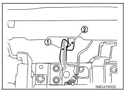
- Remove hood lock secondary control nuts and hood lock secondary control.
INSTALLATION
Installation is in the reverse order of removal.
CAUTION: Perform hood lock control inspection. Refer to DLK "Inspection".
Inspection
NOTE: If the hood lock cable is bent or deformed, replace it.
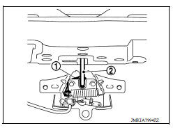
1. Check that secondary latch (1) is properly engaged with secondary striker (2) with hood's own weight.
2. Check that primary latch (1) is securely engaged with primary striker (2) when hood is dropped with hood's own weight from approximately 200 mm (7.9 in) height.
3. While operating the hood lock/fuel filler release handle assembly, carefully check that the front end of hood is raised by approximately 20.0 mm (0.79 in). Also check that hood lock/fuel filler release handle assembly returns to the original position.
4. Check that hood lock/fuel filler release handle assembly operates at 49 N (5.0 kg-f, 11.0 lb) or below.
5. Install so that static closing force of the hood is 300 - 490 N (31.0 - 50.0 kg-f, 67.4 - 110.2 lb-f).
NOTE:
- Do not exert vertical force on right side and left side of hood lock.
- Do not press simultaneously both sides.
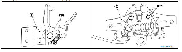
6. Check the hood lock lubrication condition. If necessary, apply a suitable multi-purpose grease to secondary latch (1) and hood lock assembly (2).
FRONT DOOR LOCK
Exploded View
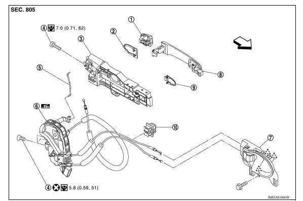
1. Door key cylinder assembly (driver
side)
Outside handle escutcheon (passenger
side)
2. Rear gasket 3. Outside handle bracket
4. Bolt 5. Door key cylinder rod (driver side) 6. Door lock assembly
7. Inside handle 8. Outside handle 9. Front gasket
10. Clip  Pawl
Pawl  Front
Front
 Hood lock control cable
HOOD LOCK CONTROL CABLE : Removal and Installation REMOVAL Disconnect hood lock control cable assembly from hood lock assembly. Refer to DLK "HOOD LOCK : Removal and Installation&quo ...
Door lock
DOOR LOCK : Removal and Installation REMOVAL Remove inside handle. Refer to DLK "INSIDE HANDLE : Removal and Installation". Remove outside handle. Refer to DLK "OUTSIDE HANDLE ...
Other materials:
Fluid cooler tube
Exploded View
1. Fluid cooler tube A 2. Copper sealing washer 3. Fluid cooler tube B
4. Bolt 5. Transaxle assembly
Removal and Installation
WARNING:
Do not open the radiator cap or drain plug when the engine is hot.
There is a danger that hot liquid
may spray out, causing serious in ...
Evaporator
Removal and Installation
REMOVAL
Remove A/C unit assembly. Refer to HA "Removal and Installation".
Disassemble A/C unit assembly and the evaporator assembly.
Remove thermo control amp. from evaporator assembly.
CAUTION:
If reusing the evaporator, mark the location of the the ...
Categories
- Manuals Home
- Nissan Versa Owners Manual
- Nissan Versa Service Manual
- Video Guides
- Questions & Answers
- External Resources
- Latest Updates
- Most Popular
- Sitemap
- Search the site
- Privacy Policy
- Contact Us

0.0077