
Nissan Versa (N17): Hood lock control cable
HOOD LOCK CONTROL CABLE : Removal and Installation
REMOVAL
- Disconnect hood lock control cable assembly from hood lock assembly. Refer to DLK "HOOD LOCK : Removal and Installation".
- Remove fender protector (LH). Refer to EXT "Removal and Installation".
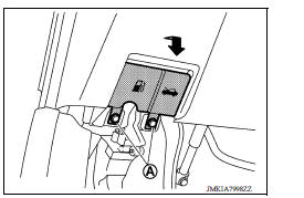
- Release hood lock control cable clips.
- Remove hood lock/fuel filler door release handle assembly bolts (A).
- Disconnect hood lock control cable assembly from hood lock/ fuel filler door release handle assembly.
6. Remove dash side finisher (LH). Refer to INT "DASH SIDE FINISHER : Removal and Installation"
7. Remove grommet on the lower dash and pull the hood lock control cable into the passenger compartment.
CAUTION: While pulling, be careful not to damage (peel) the outside of the hood lock control cable.
INSTALLATION
Installation is in the reverse order of removal.
CAUTION:
- Be careful not to bend cable too much, keep the radius 100 mm (3.94 in) or more.
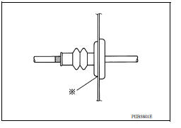
- Check that cable is not offset from the positioning grommet, and apply the sealant to the grommet (at * mark).
- Check that hood lock control cable is properly engaged with hood lock.
- After installation, perform hood adjustment procedure. Refer to DLK "HOOD ASSEMBLY : Adjustment".
- After installation, perform hood lock inspection. Refer to DLK "Inspection".
 Hood lock
HOOD LOCK : Removal and Installation REMOVAL Remove hood lock assembly bolts and hood lock assembly. Disconnect hood lock control cable assembly (2) from hood lock assembly (1). INSTALLA ...

Other materials:
Precaution
Precaution for Supplemental Restraint System
(SRS) "AIR BAG" and "SEAT BELT PRETENSIONER"
The Supplemental Restraint System such as "AIR BAG" and "SEAT BELT
PRETENSIONER", used along
with a front seat belt, helps to reduce the risk or severity of injury to the
driver and f ...
Exhaust valve timing control
Exhaust valve timing control : system diagram
Exhaust valve timing control : system description
INPUT/OUTPUT SIGNAL CHART
Sensor
Input signal to ECM
ECM function
Actuator
Crankshaft position sensor (POS)
Engine speed*1
Piston position
Exhaust valve timing c ...
Categories
- Manuals Home
- Nissan Versa Owners Manual
- Nissan Versa Service Manual
- Video Guides
- Questions & Answers
- External Resources
- Latest Updates
- Most Popular
- Sitemap
- Search the site
- Privacy Policy
- Contact Us

0.0227