Nissan Versa (N17): Cylinder head
Exploded View
Cylinder Head Bolts
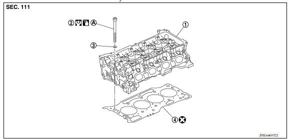
1. Cylinder head assembly 2. Cylinder head bolt 3. Washer 4. Cylinder head gasket
Valve Components
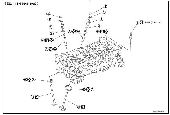
1. Spark plug 2. Valve collet 3. Valve spring retainer 4. Valve spring 5. Valve spring seat 6. Valve oil seal 7. Valve guide (INT) 8. Valve guide (EXH) 9. Valve seat (EXH) 10. Valve (EXH) 11. Valve (INT) 12. Valve seat (INT)
Removal and Installation
REMOVAL
NOTE:
When removing components such as hoses, tubes/lines, etc., cap or plug openings to prevent fluid from spilling.
- Release fuel pressure.
- Remove the following components and related parts.
- Air duct.
- Fuel tube and fuel injector.
- Water outlet.
- Exhaust manifold.
- Front cover and timing chain.
- Camshaft.
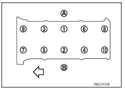
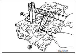
3. Remove cylinder head loosening bolts in reverse order as shown.
(A) : EXH side
(B) : INT side
 : Engine front
4. Remove cylinder head gasket.
INSTALLATION
- Install new cylinder head gasket.
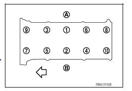
- Tighten cylinder head bolts in numerical order as shown.
(A) : EXH side
(B) : INT side
: Engine front
CAUTION:
If cylinder head bolts are reused, check their outer diameters before installation.
a. Apply new engine oil to threads and seating surfaces of bolts.
b. Tighten all bolts.
Cylinder head bolts : 40.0 N*m (4.1 kgm, 30 ftlb)
c. Turn all bolts 60 degrees clockwise (angle tightening) using Tool (A) in the specified order.
CAUTION:
Check and confirm the tightening angle by using Tool (A) or protractor. Avoid judgment by visual inspection without the tool.
Tool number : KV10112100 (BT8653A)
d. Completely loosen all bolts.
Cylinder head bolts : 0 N*m (0 kgm, 0 ftlb)
CAUTION:
In this step, loosen bolts in reverse order of that indicated as shown.
e. Tighten all bolts.
Cylinder head bolts : 40.0 N*m (4.1 kgm, 30 ftlb)
f. Turn all bolts 75 degrees clockwise (angle tightening).
g. Turn all bolts 75 degrees clockwise again (angle tightening).
3. Installation of the remaining components is in the reverse order of removal.
Disassembly and Assembly
DISASSEMBLY
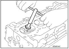
- Remove spark plug with a suitable tool.
- Remove valve lifter.
- Identify installation positions, and store lifters without mixing them up.
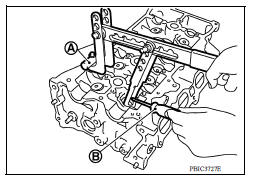
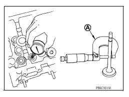
3. Remove valve collet.
- Compress valve spring with Tool (A). Remove valve collet with a magnet tool (B).
CAUTION:
Be careful not to damage valve lifter holes.
Tool number : KV10116200 (J26336B)
: KV10115900 (J2633620)
: KV10109220 ( - )
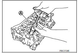
4. Remove valve spring retainer and valve spring.
5. Push valve stem to combustion chamber side, and remove valve.
- Identify installation positions, and store without mixing them up.
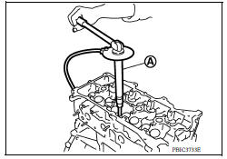
6. Remove valve oil seal using Tool (A).
Tool number : KV10107902 (J38959)
- Remove valve spring seat.
- When valve seat must be replaced.
- When valve guide must be replaced.
ASSEMBLY
- Install valve guide if removed.
- Install valve seat if removed.
- Install valve oil seal.
- Install with Tool (A) to match dimension as shown.
Height "H" : 13.2 13.8 mm (0.520 0.543 in) Tool number : KV10115600 (J38958)
4. Install valve spring seat.
5. Install valve.
- Install larger diameter to intake side.
6. Install valve spring.
NOTE:
It can be installed in either direction.
7. Install valve spring retainer.
8. Install valve collet.
- Compress valve spring with Tool (A). Install valve collet with a magnet hand (B).
CAUTION:
Be careful not to damage valve lifter holes.
- Tap valve stem edge lightly with a plastic hammer after installation to check its installed condition.
Tool number : KV10116200 (J26336B)
: KV10115900 (J2633620)
: KV10109220 ( - )
9. Install valve lifter.
10. Install spark plug with a suitable tool.
Inspection
INSPECTION AFTER REMOVAL
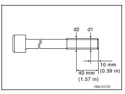
Cylinder Head Bolts Outer Diameter
- Cylinder head bolts are tightened by plastic zone tightening method. Whenever the size difference between "d1" and "d2" exceeds the limit, replace them with a new one.
Limit ("d1"-"d2"): 0.15 mm (0.0059 in)
- If reduction of outer diameter appears in a position other than "d2", use it as "d2" point.
Cylinder Head Distortion
NOTE:
When performing this inspection, cylinder block distortion should be also checking.
1. Wipe off engine oil and remove water scale (like deposit), gasket, sealant, carbon, etc. with a scraper.
CAUTION:
Use utmost care not to allow gasket debris to enter passages for engine oil or engine coolant.
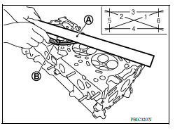
2. At each of several locations on bottom surface of cylinder head, measure the distortion in six directions.
(A) : Straightedge
(B) : Feeler gauge
- If it exceeds the limit, replace cylinder head.
INSPECTION AFTER DISASSEMBLY
VALVE DIMENSIONS
- Check the dimensions of each valve.
- If dimensions are out of the standard, replace valve and check valve seat contact.
VALVE GUIDE CLEARANCE
Valve Stem Diameter
- Measure the diameter of valve stem with micrometer (A).
Valve Guide Inner Diameter
- Measure the inner diameter of valve guide with bore gauge.
Valve Guide Clearance
- (Valve guide clearance) = (Valve guide inner diameter) - (Valve stem diameter)
- If the calculated value exceeds the limit, replace valve and/or valve guide.
VALVE GUIDE REPLACEMENT
When valve guide is removed, replace with oversized [0.2 mm (0.008 in)] valve guide.
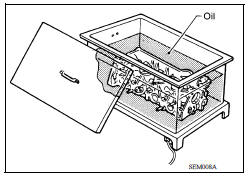
- To remove valve guide, heat cylinder head to 110 to 130C (230 to 266F) by soaking in heated oil.
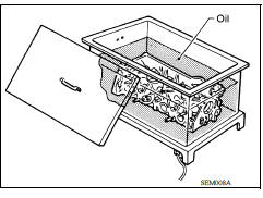
- Drive out valve guide with a press [under a 20 kN (2 ton, 2.2 US ton, 2.0 lmp ton) force] or suitable tool.
WARNING:
Cylinder head contains heat; when working, wear protective equipment to avoid getting burned.
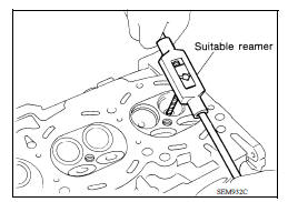
3. Ream cylinder head valve guide hole with a suitable tool.
Valve guide hole diameter (for service parts): Intake and exhaust : 9.175 9.201 mm (0.3612 0.3622 in)
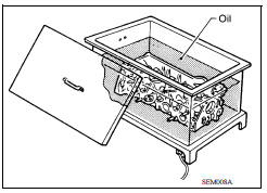
4. Heat cylinder head to 110 to 130C (230 to 266F) by soaking in heated oil.
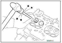
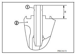
5. Using a suitable tool, press valve guide (1) from camshaft side to dimensions as shown.
Projection "H": : 11.4 11.8 mm (0.448 0.464 in)
WARNING:
Cylinder head contains heat; when working, wear protective equipment to avoid getting burned.
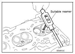
6. Apply reamer finish to valve guide with a suitable tool.
Standard 5.000 5.018 mm (0.1968 0.1975 in)
VALVE SEAT CONTACT
- After confirming that the dimensions of valve guides and valves are within the specifications, perform this procedure.
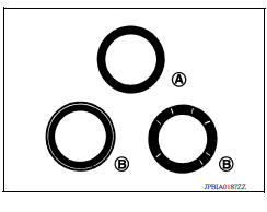
- Apply prussian blue (or white lead) onto contacting surface of valve seat to check the condition of the valve contact on the surface.
- Check if the contact area band is continuous all around the circumference.
(A) : OK
- If not, grind to adjust valve fitting and check again. If the contacting surface still has "NG" conditions (B) even after the recheck, replace valve seat.
VALVE SEAT REPLACEMENT
When valve seat is removed, replace with oversized [0.5 mm (0.020 in)] valve seat.
1. Bore out old seat until it collapses. Boring should not continue beyond the bottom face of the seat recess in cylinder head. Set the machine depth stop to ensure this.
CAUTION:
Prevent scoring cylinder head by excessive boring.
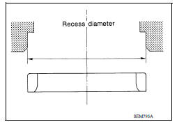
2. Ream cylinder head recess diameter for service valve seat.
Oversize [0.5 mm (0.020 in)]
Intake : 32.500 32.527 mm (1.2795 1.2805 in)
Exhaust : 26.400 26.427 mm (1.0393 1.0404 in)
- Be sure to ream in circles concentric to the valve guide center.
This will enable valve seat to fit correctly.
3. Heat cylinder head to 110 to 130C (230 to 266F) by soaking in heated oil.
4. Provide valve seats cooled well with dry ice. Pressfit valve seats into cylinder head.
WARNING:
Cylinder head contains heat; when working, wear protective equipment to avoid getting burned.
CAUTION:
Avoid directly touching cold valve seats.
5. Using a suitable tool a valve seat grinder, finish valve seat to the specified dimensions.
CAUTION:
When using a valve seat cutter, firmly grip the cutter handle with both hands. Then, press the contacting surface evenly around the valve seat to cut in a single attempt. Improper pressure or cutting several times may result in wavy valve seat.
- Using compound, grind to adjust valve fitting.
- Check again for normal contact. Refer to "VALVE SEAT CONTACT".
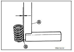
VALVE SPRING SQUARENESS
- Set a trisquare (A) along the side of valve spring and rotate spring.
Measure the maximum clearance between the top of spring and trisquare
(B) : Contact
- If it exceeds the limit, replace valve spring.
VALVE SPRING DIMENSIONS AND VALVE SPRING PRESSURE LOAD
- Check valve spring pressure with valve spring seat installed at the specified spring height.
CAUTION:
Do not remove valve spring seat from valve spring.
- If the installation load or load with valve open is out of the standard, replace valve spring (with valve spring seat).
INSPECTION AFTER INSTALLATION
- Before starting engine, check oil/fluid levels, including engine coolant and engine oil. If less than required quantity, fill to the specified level.
- Use procedure below to check for fuel leakage.
- Turn ignition switch ON (with engine stopped). With fuel pressure applied to fuel piping, check for fuel leakage at connection points.
- Start engine. With engine speed increased, check again for fuel leakage at connection points.
- Run engine to check for unusual noise and vibration.
NOTE:
If hydraulic pressure inside timing chain tensioner drops after removal and installation, slack in the guide may generate a pounding noise during and just after engine start. However, this is normal. Noise will stop after hydraulic pressure rises.
- Warm up engine thoroughly to make sure there is no leakage of fuel, exhaust gas, or any oils/fluids including engine oil and engine coolant.
- Bleed air from passages in lines and hoses, such as in cooling system.
- After cooling down engine, again check oil/fluid levels including engine oil and engine coolant. Refill to specified level, if necessary.
- Summary of the inspection items:
| Item | Before starting engine | Engine running | After engine stopped | |
| Engine coolant | Level | Leakage | Level | |
| Engine oil | Level | Leakage | Level | |
| Transmission/ transaxle fluid | A/T and CVT Models | Leakage | Level/Leakage | Leakage |
| M/T Models | Level/Leakage | Leakage | Level/Leakage | |
| Other oils and fluids* | Level | Leakage | Level | |
| Fuel | Leakage | Leakage | Leakage | |
| Exhaust gas | Leakage | |||
*Power steering fluid, brake fluid, etc.
 Rear oil seal
REAR OIL SEAL : Removal and Installation REMOVAL Remove transaxle assembly. Remove clutch cover and clutch disk (M/T models). Remove flywheel (M/T models) or drive plate (A/T or CVT model ...
Engine assembly
Exploded View 1. Engine mounting (RH) stay 2. Engine mount (RH) stay 3. Engine mounting insulator (RH) 4. Rear engine mounting bracket 5. Rear torque rod 6. Engine mounting bracket (LH) 7. ...
Other materials:
Rear oil seal
REAR OIL SEAL : Removal and Installation
REMOVAL
Remove transaxle assembly.
Remove clutch cover and clutch disk (M/T models).
Remove flywheel (M/T models) or drive plate (A/T or CVT models).
Remove rear oil seal with a suitable tool.
CAUTION:
Be careful not to damage crankshaft an ...
Cooling fan control
Cooling fan control : system diagram
Cooling fan control : system description
INPUT/OUTPUT SIGNAL CHART
Sensor
Input signal to ECM
ECM function
Actuator
Crankshaft position sensor (POS)
Camshaft position sensor (PHASE)
Engine speed*1
Piston position
Cool ...
Categories
- Manuals Home
- Nissan Versa Owners Manual
- Nissan Versa Service Manual
- Video Guides
- Questions & Answers
- External Resources
- Latest Updates
- Most Popular
- Sitemap
- Search the site
- Privacy Policy
- Contact Us

0.009