Nissan Versa (N17): System
Interior room lamp control system
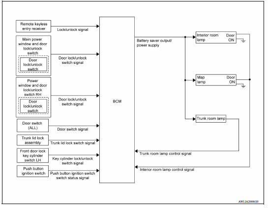
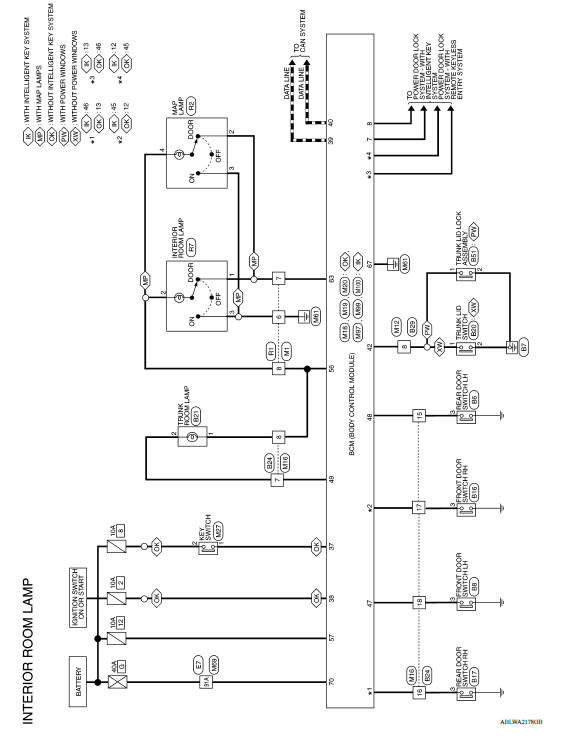
INTERIOR ROOM LAMP CONTROL SYSTEM : System Diagram
WITH INTELLIGENT KEY
WITHOUT INTELLIGENT KEY
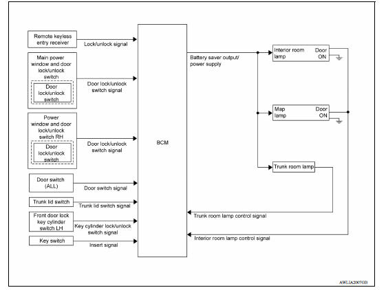
INTERIOR ROOM LAMP CONTROL SYSTEM : System Description
OUTLINE
- Interior room lamp* is controlled by the interior room lamp timer control function of the BCM.
- Trunk room lamp is controlled by the trunk room lamp control function of the BCM.
The timer control functions of the BCM activate based on inputs from the key cylinder lock/unlock switch LH, the door switches, the key switch and door lock/unlock switches.
*Interior room lamp and map lamp (if equipped) (when lamp switch is in DOOR position).
ROOM LAMP TIMER OPERATION
When the interior room lamp switch is in the DOOR position and when all conditions below are met, the BCM begins timer control (maximum 30 seconds) for interior room lamp ON/OFF.
- When the front door LH is unlocked with key fob, main power window and door lock/unlock switch, power window and door lock/unlock switch RH or front door lock assembly LH (key cylinder switch).
- When a door opens → closes and the push-button ignition switch is not pressed (with Intelligent Key).
- When a door opens → closes and the key is not inserted in the ignition switch (without Intelligent Key).
Timer control is cancelled under the following conditions.
- When the front door LH is locked with key fob, main power window and door lock/unlock switch, power window and door lock/unlock switch RH or front door lock assembly LH (key cylinder switch).
- A door is opened (door switch turns ON).
- Ignition switch is turned ON.
Interior lamp operational settings can be changed with the function setting of CONSULT.
INTERIOR LAMP BATTERY SAVER CONTROL
If an interior lamp is left ON and does not turn OFF even when the doors are closed, the BCM turns off power to the interior lamps automatically to save the battery 10 minutes after the ignition switch is turned OFF.
The BCM controls power and ground to all interior lamps.
After the battery saver system turns the lamps OFF, the lamps will illuminate again when
- a signal is received from a key fob, main power window and door lock/unlock switch, power window and door lock/unlock switch RH or when the front door lock assembly LH (key cylinder switch) is locked or unlocked
- a door is opened or closed
- the key is removed from or inserted into the ignition switch (without Intelligent Key).
The interior lamp battery saver control time period can be changed with the function setting of CONSULT.
Illumination control system
ILLUMINATION CONTROL SYSTEM : System Diagram
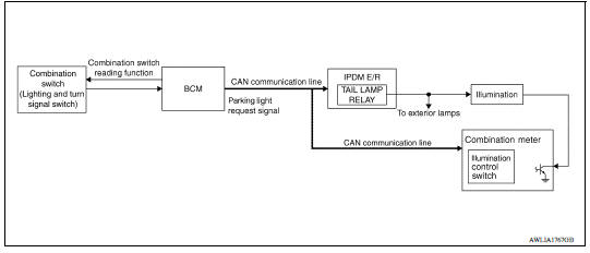
ILLUMINATION CONTROL SYSTEM : System Description
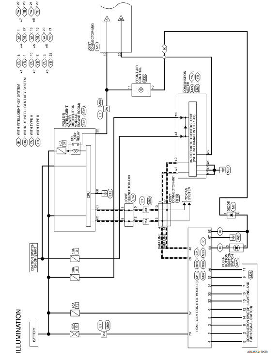
The illumination lamps operation is dependent upon the position of the combination switch (lighting and turn signal switch). When the combination switch (lighting and turn signal switch) is placed in the 1ST or 2ND position the BCM (body control module) receives input requesting the parking lamps to illuminate. This input is communicated to the IPDM E/R (intelligent power distribution module engine room) via the CAN communication lines. The CPU (central processing unit) of the IPDM E/R controls the tail lamp relay coil. When energized, this relay directs power to the parking and illumination lamps, which then illuminate.
BATTERY SAVER CONTROL
When the combination switch (lighting and turn signal switch) is in the 1st or 2nd position and the ignition switch is turned from ON or ACC to OFF, the battery saver control feature is activated. Under this condition, the illumination lamps remain illuminated for 10 minutes unless the combination switch (lighting and turn signal switch) position is changed. If the combination switch (lighting and turn signal switch) position is changed, then the illumination lamps are turned off after a 15 second delay. When the combination switch (lighting and turn signal switch) is turned from OFF to 1st or 2nd position after illumination lamps have been turned off by the battery saver control, the illumination lamps illuminate again.
DIAGNOSIS SYSTEM (BCM) (WITH INTELLIGENT KEY SYSTEM)
COMMON ITEM
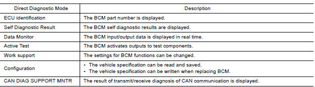
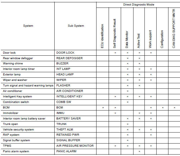
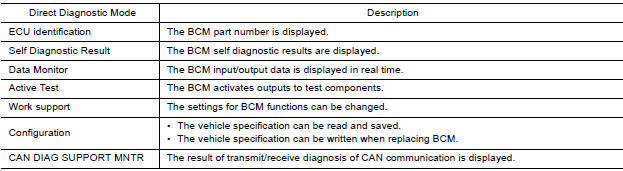
COMMON ITEM : CONSULT Function (BCM - COMMON ITEM)
APPLICATION ITEM
CONSULT performs the following functions via CAN communication with BCM.
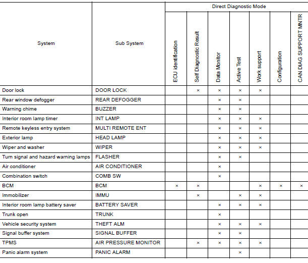
SYSTEM APPLICATION
BCM can perform the following functions.
DOOR LOCK
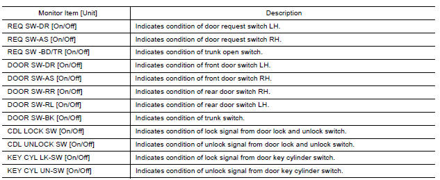
DOOR LOCK : CONSULT Function (BCM - DOOR LOCK)
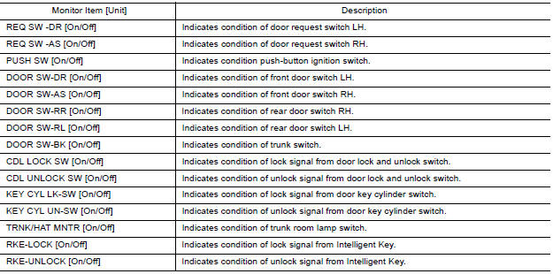
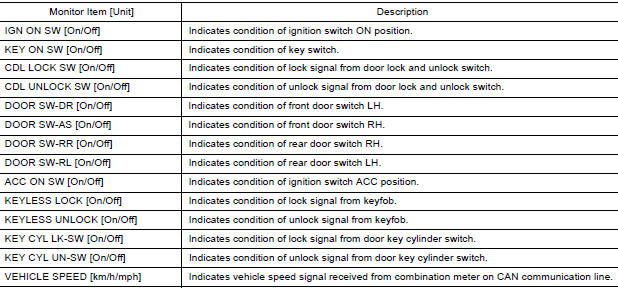
DATA MONITOR
ACTIVE TEST

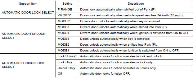
WORK SUPPORT
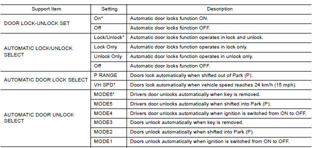
*: Initial setting
INT LAMP
INT LAMP : CONSULT Function (BCM - INT LAMP)
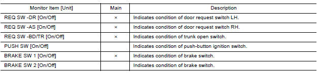
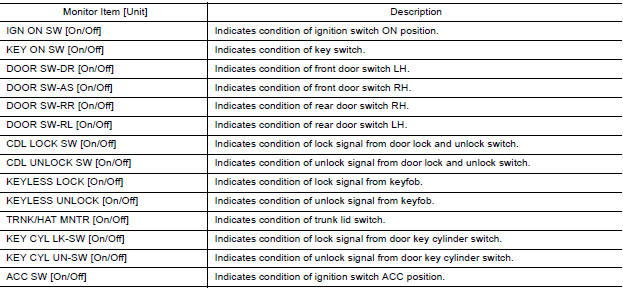
DATA MONITOR
ACTIVE TEST

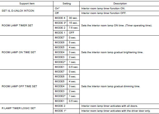
WORK SUPPORT
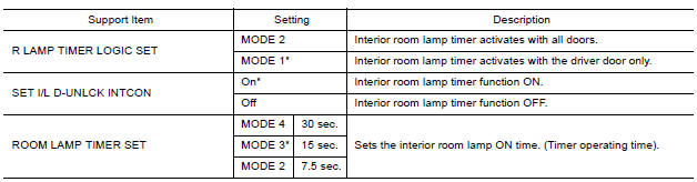
*: Initial setting
INTELLIGENT KEY
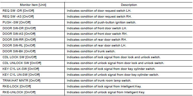
INTELLIGENT KEY : CONSULT Function (BCM - INTELLIGENT KEY)
SELF DIAGNOSTIC RESULT
Refer to BCS "DTC Index".
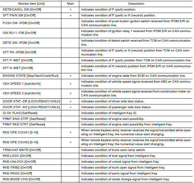
DATA MONITOR
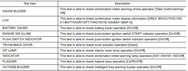
ACTIVE TEST

WORK SUPPORT
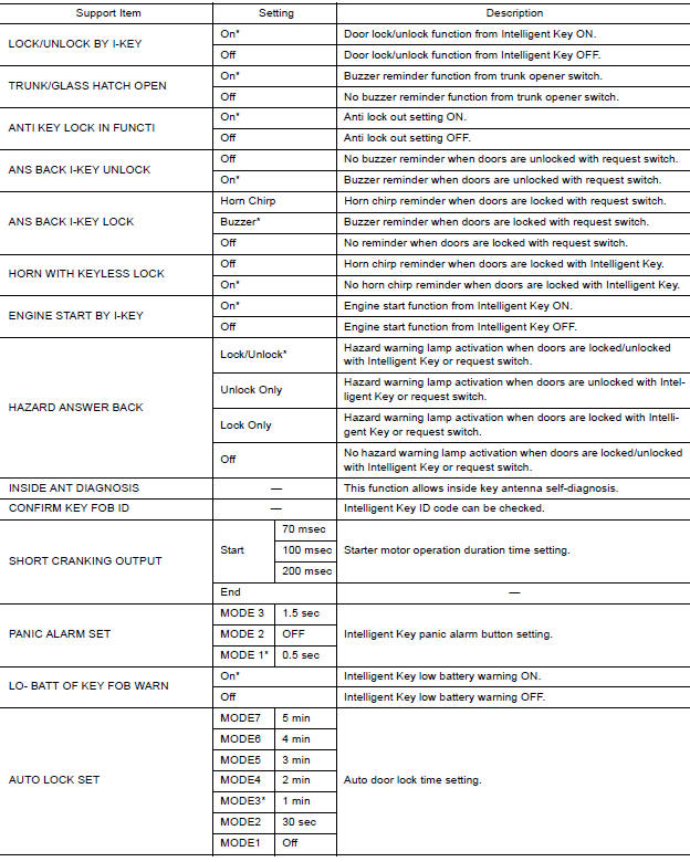
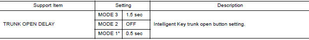
*: Initial Setting
BATTERY SAVER
BATTERY SAVER : CONSULT Function (BCM - BATTERY SAVER)
DATA MONITOR
ACTIVE TEST

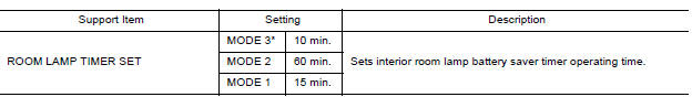
WORK SUPPORT
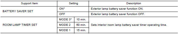
*: Initial setting
DIAGNOSIS SYSTEM (BCM) (WITHOUT INTELLIGENT KEY SYSTEM)
COMMON ITEM
COMMON ITEM : CONSULT Function (BCM - COMMON ITEM)
APPLICATION ITEM
CONSULT performs the following functions via CAN communication with BCM.
SYSTEM APPLICATION
BCM can perform the following functions.
DOOR LOCK
DOOR LOCK : CONSULT Function (BCM - DOOR LOCK)
DATA MONITOR
ACTIVE TEST

WORK SUPPORT
* : Initial setting
INT LAMP
INT LAMP : CONSULT Function (BCM - INT LAMP)
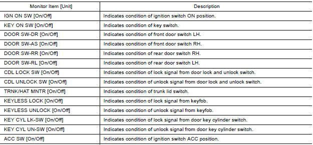
DATA MONITOR
ACTIVE TEST

WORK SUPPORT
* : Initial setting
BATTERY SAVER
BATTERY SAVER : CONSULT Function (BCM - BATTERY SAVER)
DATA MONITOR
ACTIVE TEST

WORK SUPPORT
* : Initial setting
ECU DIAGNOSIS INFORMATION
BCM
List of ECU Reference
WITH INTELLIGENT KEY
| ECU | Reference |
| BCM | BCS "Reference Value" |
| BCS "Fail-safe" | |
| BCS "DTC Inspection Priority Chart" | |
| BCS "DTC Index" |
WITHOUT INTELLIGENT KEY
| ECU | Reference |
| BCM | BCS "Reference Value" |
| BCS "Fail-safe" | |
| BCS "DTC Inspection Priority Chart" | |
| BCS "DTC Index" |
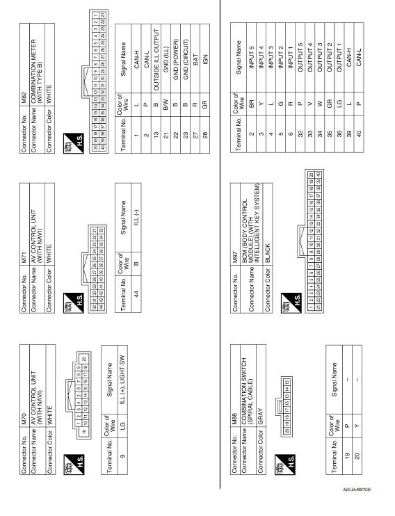
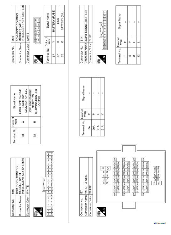
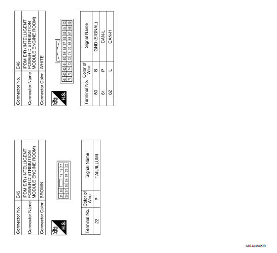
WIRING DIAGRAM
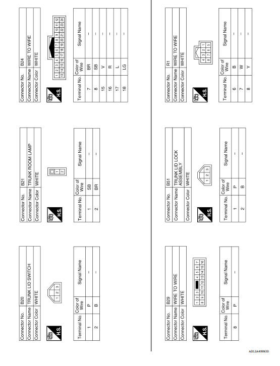
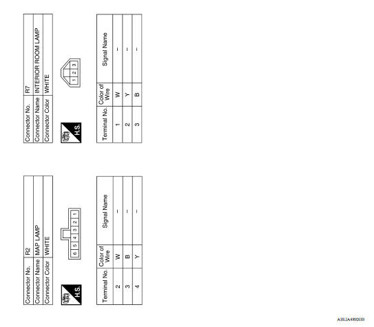
INTERIOR ROOM LAMP CONTROL SYSTEM
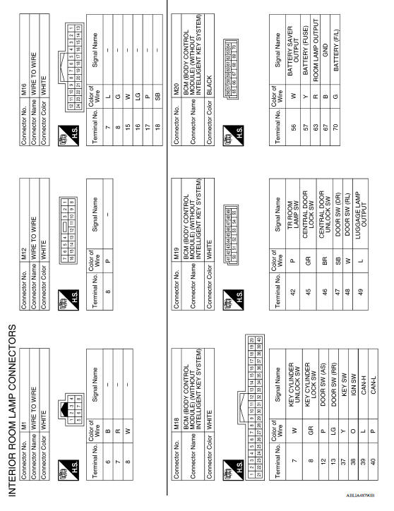
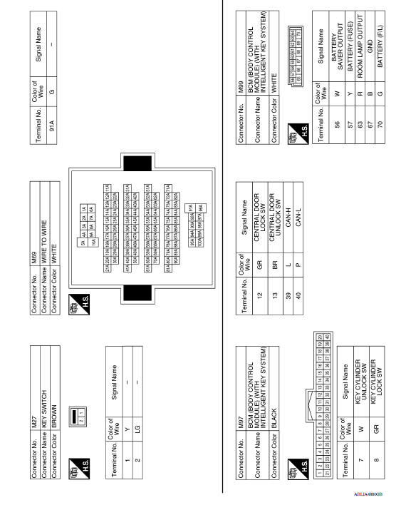
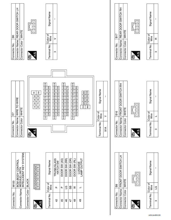
Wiring Diagram
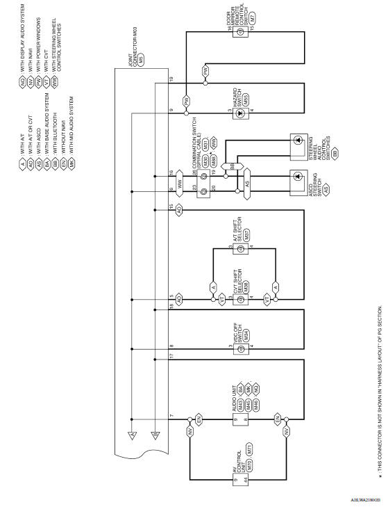
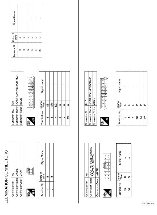
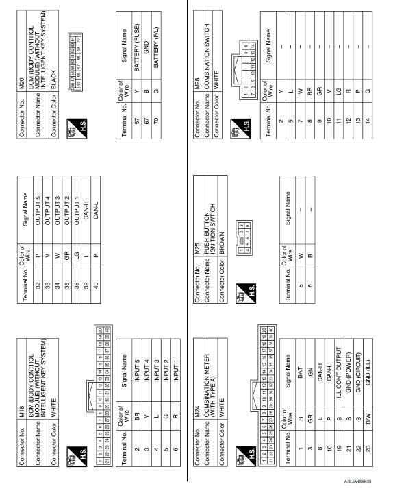
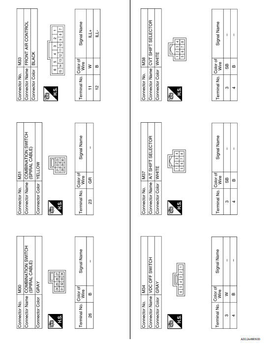
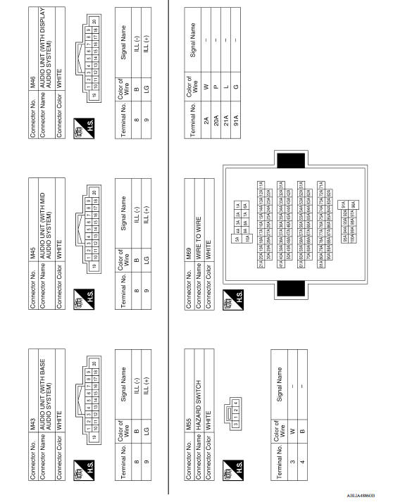
ILLUMINATION
Wiring Diagram
BASIC INSPECTION
 Precautions
Diagnosis and repair workflow
Work Flow OVERALL SEQUENCE DETAILED FLOW 1.INTERVIEW FOR MALFUNCTION Interview the symptom to the customer. >> GO TO 2. 2.SYMPTOM CHECK Check the symptom from the customer's informati ...
Other materials:
Air cleaner and air duct
Exploded View
1. Clamp 2. PCV hose 3. Clamp
4. Mount rubber 5. Air duct (inlet) 6. Air cleaner body
7. Grommet 8. Air cleaner filter 9. Air cleaner cover
10. Mass air flow sensor 11. Air duct 12. Clamp
Removal and Installation
REMOVAL
NOTE:
Mass air flow sensor is removable as an assemb ...
Intake manifold
Exploded View
1. EVAP canister purge volume control
solenoid valve
2. Hose clamp 3. Vacuum hose
4. PCV hose 5. Hose clamp 6. Intake manifold support
7. Gasket 8. Intake manifold 9. Electric throttle control actuator
10. Gasket 11. EVAP service port
A. To air duct B. To centralized underf ...
Categories
- Manuals Home
- Nissan Versa Owners Manual
- Nissan Versa Service Manual
- Video Guides
- Questions & Answers
- External Resources
- Latest Updates
- Most Popular
- Sitemap
- Search the site
- Privacy Policy
- Contact Us

0.0065