Nissan Versa (N17): IPDM-E Branch line circuit
Diagnosis Procedure
1.CHECK CONNECTOR
1. Turn the ignition switch OFF.
2. Disconnect the battery cable from the negative terminal.
3. Check the terminals and connectors of the IPDM E/R for damage, bend and loose connection (unit side and connector side).
Is the inspection result normal?
YES >> GO TO 2.
NO >> Repair the terminal and connector.
2.CHECK HARNESS FOR OPEN CIRCUIT
1. Disconnect the connector of IPDM E/R.
2. Check the resistance between the IPDM E/R harness connector terminals.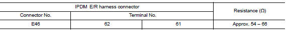
Is the measurement value within the specification?
YES >> GO TO 3.
NO >> Repair the IPDM E/R branch line.
3.CHECK POWER SUPPLY AND GROUND CIRCUIT
Check the power supply and the ground circuit of the IPDM E/R. Refer to the following.
- With Intelligent Key system: PCS"Diagnosis Procedure"
- Without Intelligent Key system: PCS "Diagnosis Procedure"
Is the inspection result normal?
YES (Present error)>>Replace the IPDM E/R. Refer to the following.
- With Intelligent Key system: PCS "Removal and Installation"
- Without Intelligent Key system: PCS "Removal and Installation"
YES (Past error)>>Error was detected in the IPDM E/R branch line.
NO >> Repair the power supply and the ground circuit.
 ABS Branch line circuit
Diagnosis Procedure 1.CHECK CONNECTOR 1. Turn the ignition switch OFF. 2. Disconnect the battery cable from the negative terminal. 3. Check the terminals and connectors of the ABS actuator and ele ...
TCM Branch line circuit
Diagnosis Procedure 1.CHECK CONNECTOR 1. Turn the ignition switch OFF. 2. Disconnect the battery cable from the negative terminal. 3. Check the following terminals and connectors for damage, bend ...
Other materials:
Trunk lid
WARNING
Do not drive with the trunk lid open. This
could allow dangerous exhaust gases
to be drawn into the vehicle. For additional
information, refer to "Exhaust
gas (carbon monoxide)" in the "Starting
and driving" section of this manual.
Closely supervise children when they
are a ...
Brakes
If the brakes do not operate properly, have the
brakes checked. It is recommended that you visit
a NISSAN dealer for this service.
Self-adjusting brakes
Your vehicle is equipped with self-adjusting
brakes.
The front disc-type brakes self-adjust every time
the brake pedal is applied. The rea ...
Categories
- Manuals Home
- Nissan Versa Owners Manual
- Nissan Versa Service Manual
- Video Guides
- Questions & Answers
- External Resources
- Latest Updates
- Most Popular
- Sitemap
- Search the site
- Privacy Policy
- Contact Us

0.0046