Nissan Versa (N17): IPDM E/R
Removal and Installation
CAUTION: IPDM E/R integrated relays are not serviceable parts and must not be removed from the unit.
REMOVAL
1. Disconnect the battery negative terminal. Refer to PG-63, "Removal and Installation".
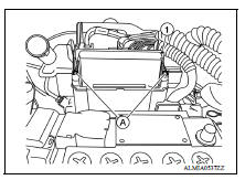
2. Remove the IPDM E/R cover.
3. Release the pawls (A) and separate the IPDM E/R (1) from the case.
4. Disconnect the harness connectors and remove the IPDM E/R.
INSTALLATION
Installation is in the reverse order of removal.
IPDM E/R (WITHOUT I-KEY)
 Power supply and ground circuit
Diagnosis Procedure Regarding Wiring Diagram information, refer to PCS "Wiring Diagram". 1. CHECK FUSE AND FUSIBLE LINKS Check that the following IPDM E/R fuse or fusible links are not ...
Precautions
Precaution for Supplemental Restraint System (SRS) "AIR BAG" and "SEAT BELT PRE-TENSIONER" The Supplemental Restraint System such as "AIR BAG" and "SEAT BELT PRE-TENSIONER", us ...
Other materials:
Exterior front
1. Engine hood
2. Windshield
3. Wiper and washer switch
4. Power windows (if so equipped)
5. Door locks. NISSAN Intelligent Key
(if so equipped). Key fob (if so equipped). Keys
6. Mirrors
7. Tire pressure. Flat tire. Tire chains
8. Headlight and turn signal switch. Replacing bulbs
9. Fo ...
Push-button ignition switch (if so equipped)
WARNING
Do not operate the push-button ignition
switch while driving the vehicle except in
an emergency. (The engine will stop when
the ignition switch is pushed 3 consecutive
times in quick succession or the ignition
switch is pushed and held for more
than 2 seconds.) If the engine stops ...
Categories
- Manuals Home
- Nissan Versa Owners Manual
- Nissan Versa Service Manual
- Video Guides
- Questions & Answers
- External Resources
- Latest Updates
- Most Popular
- Sitemap
- Search the site
- Privacy Policy
- Contact Us

0.0057