Nissan Versa (N17): Power supply and ground circuit
Diagnosis Procedure
Regarding Wiring Diagram information, refer to PCS "Wiring Diagram".
1. CHECK FUSE AND FUSIBLE LINKS
Check that the following IPDM E/R fuse or fusible links are not blown.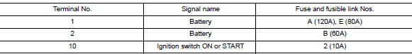
Is the fuse blown?
YES >> Replace the blown fuse or fusible link after repairing the affected circuit.
NO >> GO TO 2
2. CHECK BATTERY POWER SUPPLY CIRCUIT
1. Turn ignition switch OFF.
2. Disconnect IPDM E/R.
3. Check voltage between IPDM E/R connectors and ground.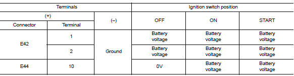
Is the measurement value normal?
YES >> GO TO 3
NO >> Repair or replace harness.
3. CHECK GROUND CIRCUIT
1. Turn ignition switch OFF.
2. Check continuity between IPDM E/R connectors and ground.
Does continuity exist?
YES >> Inspection End.
NO >> Repair or replace harness.
REMOVAL AND INSTALLATION
 B2099 Ignition relay off stuck
Description IPDM E/R operates the ignition relay when it receives an ignition switch ON signal from BCM via CAN communication. Turn the ignition relay OFF by pressing the push-button igniti ...
IPDM E/R
Removal and Installation CAUTION: IPDM E/R integrated relays are not serviceable parts and must not be removed from the unit. REMOVAL 1. Disconnect the battery negative terminal. Refer to PG-63, ...
Other materials:
Seats
WARNING
Do not ride in a moving vehicle when
the seatback is reclined. This can be
dangerous. The shoulder belt will not
be against your body. In an accident,
you could be thrown into it and receive
neck or other serious injuries. You
could also slide under the lap belt and
recei ...
Meters and gauges
Type A (if so equipped)
1. Tachometer
2. Speedometer
3. Fuel gauge
4. Odometer
Twin trip odometer
Trip computer
5. Continuously Variable Transmission
(CVT) position indicator (if so equipped)
Automatic Transmission (A/T) position
indicator (if so equipped)
6. Instrument brightness con ...
Categories
- Manuals Home
- Nissan Versa Owners Manual
- Nissan Versa Service Manual
- Video Guides
- Questions & Answers
- External Resources
- Latest Updates
- Most Popular
- Sitemap
- Search the site
- Privacy Policy
- Contact Us

0.0047