Nissan Versa (N17): Key interlock cable
Exploded View
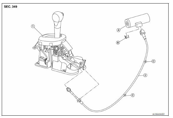
1. CVT shift selector assembly 2. Key interlock cable A: Key cylinder B: Lock plate C: Clip
Removal and Installation
REMOVAL
CAUTION: Always apply the parking brake before performing removal and installation.
- Move the shift selector to the "N" position.
- Remove the shift selector handle. Refer to TM "Disassembly and Assembly".
- Remove the center console. Refer to IP "Removal and Installation".
- Move the shift selector to the "P" position.
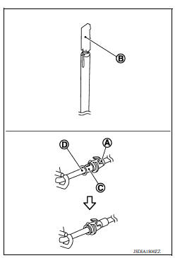
- Press the pawls (B) of the key interlock cable slider (A) while sliding it in the direction of the casing cap (C), and separate the adjusting holder (D) and slider.
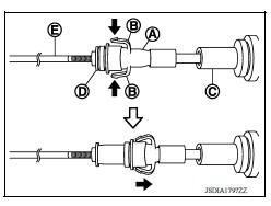
(E) :Key interlock rod
- Remove the key interlock cable from the CVT shift selector assembly.
- Remove the instrument lower panel LH. Refer to IP "Removal and Installation".
- Remove the steering column upper and lower covers. Refer to IP "Removal and Installation".
- Remove the center console lower. Refer to IP "Removal and Installation".
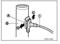
- Lift lock plate (
 A) in the
direction of the arrow (
A) in the
direction of the arrow (  C) and
remove
in the direction of the arrow
C) and
remove
in the direction of the arrow - Remove the key interlock cable from the key cylinder.
- Disengage the clips and remove the key interlock cable from the vehicle.
(1) :Key interlock cable (B) :Key cylinder
INSTALLATION
- Installation is in the reverse order of removal.
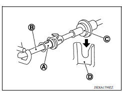
- Temporarily install the adjust holder (A) to the key interlock rod (B).
- Install the casing cap (C) to the cable bracket (D) on the CVT shift selector assembly.
CAUTION:
- Do not bend or twist key interlock cable excessively when installing.
- After installing key interlock cable to cable bracket (D) on CVT shift selector assembly, make sure casing caps (C) is firmly secured in cable bracket (D) on CVT shift selector assembly.
- If casing cap (C) is loose [less than 39.2 N (4.0 kg, 8.8 lb) removing force], replace key interlock cable.
- Slide the slider (A) toward the key interlock rod (D) while pressing the pull lock (B) down to securely connect the adjust holder (C) with the key interlock rod (D).
CAUTION:
- Do not press tabs when holding slider (A).
- Do not apply any side to side force to key interlock rod (D) when sliding slider (A).
Inspection
INSPECTION AFTER INSTALLATION
- Check the CVT operation. If a malfunction is found, adjust the CVT position. Refer to TM "Inspection and Adjustment".
- Make sure the key can be removed only when the shift selector is in the "P" position.
- Make sure the ignition switch will not turn to LOCK position when the shift selector is not in the "P" position.
 Control cable
Exploded View 1. Bracket B 2. Lock plate 3. Transaxle assembly 4. Bracket A 5. Control cable 6. CVT shift selector assembly A: Manual lever B: Grommet Removal and Installation CAUTION: Alw ...
TCM
Exploded View 1. TCM 2. Bracket 3. Clip Front Removal and Installation CAUTION: When replacing TCM, note the "CVTF DETERIORATION DATE" value displayed on CONSULT "CONFORM CVTF DETERIORTN" ...
Other materials:
U0101 can comm circuit
Description
CAN (Controller Area Network) is a serial communication line for real time
application. It is an onvehicle multiplex
communication line with high data communication speed and excellent error
detection ability. Many electronic
control units are equipped onto a vehicle, and each con ...
Lock-up control
LOCK-UP CONTROL : System Description
SYSTEM DIAGRAM
DESCRIPTION
Controls for improvement of the transmission efficiency by engaging the
torque converter clutch in the
torque converter and eliminating slip of the converter. Achieves comfortable
driving with slip control of the
t ...
Categories
- Manuals Home
- Nissan Versa Owners Manual
- Nissan Versa Service Manual
- Video Guides
- Questions & Answers
- External Resources
- Latest Updates
- Most Popular
- Sitemap
- Search the site
- Privacy Policy
- Contact Us

0.0047