Nissan Versa (N17): Key switch signal circuit (without intelligent key)
Description
Transmits a key switch signal to the BCM.
Component Function Check
1. CHECK BCM INPUT SIGNAL
Select "DATA MONITOR" for "BCM" and check the "KEY ON SW" monitor value.
KEY ON SW
When key is inserted into key cylinder : ON
When key is removed from key cylinder : OFF
Is the inspection result normal?
YES >> Inspection End.
NO >> Refer to WCS "Diagnosis Procedure".
Diagnosis Procedure
Regarding Wiring Diagram information, refer to WCS "Wiring Diagram".
1. CHECK FUSE
Check if the key switch 10A fuse [No. 8, located in the fuse block (J/B)] is blown.
Is the fuse blown?
YES >> Replace the fuse after repairing the affected circuit.
NO >> GO TO 2
2. CHECK BCM INPUT SIGNAL
Check voltage between BCM harness connector M18 terminal 37 and ground.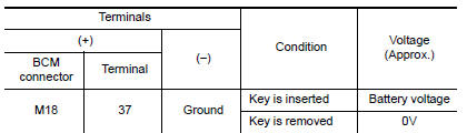
Is the inspection result normal?
YES >> Inspection End.
NO >> GO TO 3
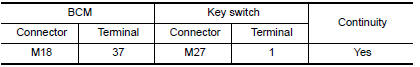
3. CHECK KEY SWITCH CIRCUIT
1. Disconnect BCM connector M18 and key switch.
2. Check continuity between BCM harness connector M18 terminal 37 and key
switch harness connector
M27 terminal 1.
3. Check continuity between BCM harness connector M18 terminal 37 and ground.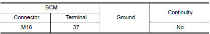
Is the inspection result normal?
YES >> GO TO 4
NO >> Repair or replace harness.
4. CHECK KEY SWITCH POWER SUPPLY CIRCUIT
Check voltage between key switch harness connector M27 terminal 2 and ground.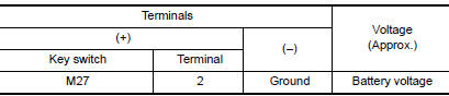
Is the inspection result normal?
YES >> Replace key switch.
NO >> Repair or replace harness.
Component Inspection
1. CHECK KEY SWITCH
1. Turn ignition switch OFF.
2. Disconnect key switch.
3. Check continuity between key switch terminals 1 and 2.
1 -2
When key is inserted into key cylinder : Continuity should exist.
When key is removed from key cylinder : Continuity should not exist.
Is the inspection result normal?
YES >> Inspection End.
NO >> Replace key switch.
 Seat belt buckle switch signal circuit
Other materials:
U0101 can comm circuit
Description
CAN (Controller Area Network) is a serial communication line for real time
application. It is an onvehicle multiplex
communication line with high data communication speed and excellent error
detection ability. Many electronic
control units are equipped onto a vehicle, and each con ...
ABS Warning lamp
Component Function Check
1.CHECK ABS WARNING LAMP FUNCTION
Check that ABS warning lamp in combination meter turns ON for approximately 2
seconds after ignition switch
is turned ON.
Is the inspection result normal?
YES >> Inspection End.
NO >> Proceed to diagnosis procedure. Ref ...
Categories
- Manuals Home
- Nissan Versa Owners Manual
- Nissan Versa Service Manual
- Video Guides
- Questions & Answers
- External Resources
- Latest Updates
- Most Popular
- Sitemap
- Search the site
- Privacy Policy
- Contact Us

0.0046