Nissan Versa (N17): Line pressure test
Work Procedure
INSPECTION
- Inspect the amount of engine oil. Replenish the engine oil if necessary. Refer to LU, "Inspection".
- Drive for about 10 minutes to warm up the vehicle so that the A/T fluid temperature is to 50 to 80C (122 to 176F).
- Inspect the amount of ATF. Replenish if necessary. Refer to TM, "Inspection".
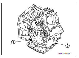
- Remove fluid pressure detection plug.
- Install the joint pipe adapter [SST: KV31103600 ( - )],
adapter [SST: 25054000 (J-25695-4)], and oil pressure gauge
set (commercial service tool).
NOTE: When using oil pressure gauge, be sure to use O-ring attached to fluid pressure detection plug.
- Securely engage parking brake so that the tires do not turn.
- Start the engine.
- Measure the line pressure at both idle and the stall speed.
CAUTION: Keep brake pedal pressed all the way down during measurement.
1 : "D" position fluid pressure detection plug
2 : "R" position fluid pressure detection plug
Line pressure : TM, "Line Pressure"
9. Install O-rig to fluid pressure detection plug.
CAUTION:
- Do not reuse O-ring.
- Apply ATF to O-ring.
10. Install fluid pressure detection plug.
 : 7.4 N*m (1.70 lb-m, 66
in-lb)
: 7.4 N*m (1.70 lb-m, 66
in-lb)
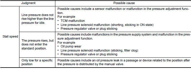
JUDGMENT 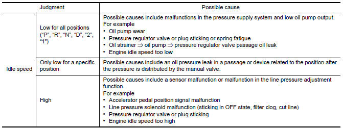
DTC/Circuit diagnosis
 Stall test
Work Procedure INSPECTION Inspect the amount of engine oil. Replenish the engine oil if necessary. Refer to LU "Inspection". Drive for about 10 minutes to warm up the vehicle so th ...
U0073 Communication bus a off
DTC Logic DTC Trouble diagnosis name DTC detecting condition Possible causes U0073 Control Module Communication Bus "A" Off When the ignition switch is ON, ...
Other materials:
Service data and specifications
(sds)
General Specification
GENERAL SPECIFICATIONS
Engine type
HR16DE
Cylinder arrangement
Inline 4
Displacement &nbs ...
Front seat
DRIVER SIDE
DRIVER SIDE : Exploded View
WITH REMOVABLE HEADREST
1. Armrest (if equipped) 2. Seat cushion outer finisher (RH) 3. Seat belt
buckle
4. Seat cushion trim 5. Seat cushion pad 6. Seat cushion frame
7. Seat cushion outer finisher (LH) 8. Lift lever (if equipped) 9. Lift lever
c ...
Categories
- Manuals Home
- Nissan Versa Owners Manual
- Nissan Versa Service Manual
- Video Guides
- Questions & Answers
- External Resources
- Latest Updates
- Most Popular
- Sitemap
- Search the site
- Privacy Policy
- Contact Us

0.0057