Nissan Versa (N17): M&A Branch line circuit
Diagnosis Procedure
1.CHECK CONNECTOR
1. Turn the ignition switch OFF.
2. Disconnect the battery cable from the negative terminal.
3. Check the terminals and connectors of the combination meter for damage, bend and loose connection (unit side and connector side).
Is the inspection result normal?
YES >> GO TO 2.
NO >> Repair the terminal and connector.
2.CHECK HARNESS FOR OPEN CIRCUIT
1. Disconnect the connector of combination meter.
2. Check the resistance between the combination meter harness connector terminals.
NOTE: Check the vehicle type confirm the service information. Refer to MWI "Information".
- Models with Type A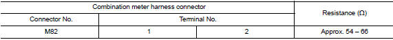
- Models with Type B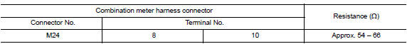
Is the measurement value within the specification?
YES >> GO TO 3.
NO >> Repair the combination meter branch line.
3.CHECK POWER SUPPLY AND GROUND CIRCUIT
Check the power supply and the ground circuit of the combination meter. Refer to the following.
- TYPE A: MWI "COMBINATION METER : Diagnosis Procedure"
- TYPE B: MWI"COMBINATION METER : Diagnosis Procedure"
Is the inspection result normal?
YES (Present error)>>Replace the combination meter. Refer to the following.
- TYPE A: MWI "Removal and Installation"
- TYPE B: MWI "Removal and Installation"
YES (Past error)>>Error was detected in the combination meter branch line.
NO >> Repair the power supply and the ground circuit.
 EPS Branch line circuit
Diagnosis Procedure 1.CHECK CONNECTOR 1. Turn the ignition switch OFF. 2. Disconnect the battery cable from the negative terminal. 3. Check the terminals and connectors of the EPS control unit for ...
STRG Branch line circuit
Diagnosis Procedure 1.CHECK CONNECTOR 1. Turn the ignition switch OFF. 2. Disconnect the battery cable from the negative terminal. 3. Check the terminals and connectors of the steering angle sen ...
Other materials:
Shift control
SHIFT CONTROL : System Description
SYSTEM DIAGRAM
DESCRIPTION
To select the gear ratio that can give the driving force to meet driver's
intent or vehicle situation, the vehicle
driving condition such as vehicle speed or accelerator pedal position is
detected and the most appropriate
g ...
Output speed sensor
Exploded View
1. Transaxle assembly 2. Output speed sensor 3. O-ring
Front Genuine
NISSAN CVT Fluid NS-3
Removal and Installation
REMOVAL
Disconnect the harness connector from output speed sensor.
NOTE:
Lift up the vehicle and perform the work from rear of the transaxle
asse ...
Categories
- Manuals Home
- Nissan Versa Owners Manual
- Nissan Versa Service Manual
- Video Guides
- Questions & Answers
- External Resources
- Latest Updates
- Most Popular
- Sitemap
- Search the site
- Privacy Policy
- Contact Us

0.0047