Nissan Versa (N17): Main line between IPDM-E and DLC circuit
Diagnosis Procedure
1.CHECK CONNECTOR
1. Turn the ignition switch OFF.
2. Disconnect the battery cable from the negative terminal.
3. Check the following terminals and connectors for damage, bend and loose connection (connector side and harness side).
- Harness connector E7
- Harness connector M69
Is the inspection result normal?
YES >> GO TO 2.
NO >> Repair the terminal and connector.
2.CHECK HARNESS CONTINUITY (OPEN CIRCUIT)
1. Disconnect the following harness connectors.
- IPDM E/R
- Harness connectors E7 and M69
2. Check the continuity between the IPDM E/R harness connector and the
harness connector.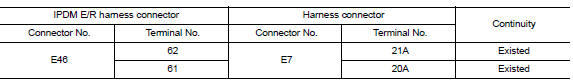
Is the inspection result normal?
YES >> GO TO 3.
NO >> Repair the main line between the IPDM E/R and the harness connector E7.
3.CHECK HARNESS CONTINUITY (OPEN CIRCUIT)
Check the continuity between the harness connector and the data link
connector.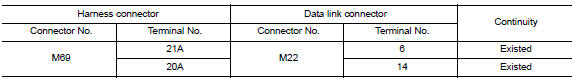
Is the inspection result normal?
YES (Present error)>>Check CAN system type decision again.
YES (Past error)>>Error was detected in the main line between the IPDM E/R and the data link connector.
NO >> Repair the main line between the harness connector M69 and the data link connector.
 CAN Communication system
ECM Branch line circuit
Diagnosis Procedure 1.CHECK CONNECTOR 1. Turn the ignition switch OFF. 2. Disconnect the battery cable from the negative terminal. 3. Check the terminals and connectors of the ECM for damage, bend ...
Other materials:
Front oil seal
FRONT OIL SEAL : Removal and Installation
REMOVAL
1. Remove the following parts.
Remove wheel and tire.
Front fender protector (RH).
Drive belt.
Crankshaft pulley.
2. Remove front oil seal with ...
EVAP canister vent control valve
Exploded View
1. EVAP canister 2. O-ring 3. EVAP canister vent control valve
4. EVAP canister vent control valve hose
Removal and Installation
NOTE:
The EVAP canister vent control valve can be removed without removing the EVAP
canister.
REMOVAL
Remove the EVAP canister protector cov ...
Categories
- Manuals Home
- Nissan Versa Owners Manual
- Nissan Versa Service Manual
- Video Guides
- Questions & Answers
- External Resources
- Latest Updates
- Most Popular
- Sitemap
- Search the site
- Privacy Policy
- Contact Us

0.0047