Nissan Versa (N17): ECM Branch line circuit
Diagnosis Procedure
1.CHECK CONNECTOR
1. Turn the ignition switch OFF.
2. Disconnect the battery cable from the negative terminal.
3. Check the terminals and connectors of the ECM for damage, bend and loose connection (unit side and connector side).
Is the inspection result normal?
YES >> GO TO 2.
NO >> Repair the terminal and connector.
2.CHECK HARNESS FOR OPEN CIRCUIT
1. Disconnect the connector of ECM.
2. Check the resistance between the ECM harness connector terminals.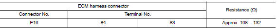
Is the measurement value within the specification?
YES >> GO TO 3.
NO >> Repair the ECM branch line.
3.CHECK POWER SUPPLY AND GROUND CIRCUIT
Check the power supply and the ground circuit of the ECM. Refer to EC"Diagnosis Procedure".
Is the inspection result normal?
YES (Present error)>>Replace the ECM. Refer to EC "Removal and Installation".
YES (Past error)>>Error was detected in the ECM branch line.
NO >> Repair the power supply and the ground circuit.
 Main line between IPDM-E and DLC
circuit
Main line between IPDM-E and DLC
circuit
Diagnosis Procedure 1.CHECK CONNECTOR 1. Turn the ignition switch OFF. 2. Disconnect the battery cable from the negative terminal. 3. Check the following terminals and connectors for damage, bend ...
ABS Branch line circuit
Diagnosis Procedure 1.CHECK CONNECTOR 1. Turn the ignition switch OFF. 2. Disconnect the battery cable from the negative terminal. 3. Check the terminals and connectors of the ABS actuator and ele ...
Other materials:
Line pressure test
Work Procedure
INSPECTION
Inspect the amount of engine oil. Replenish the engine oil if necessary.
Refer to LU, "Inspection".
Drive for about 10 minutes to warm up the vehicle so that the A/T fluid
temperature is to 50 to 80C (122
to 176F).
Inspect the amount of ATF. Rep ...
Shift position indicator circuit
Component Parts Function Inspection
1.CHECK SHIFT POSITION INDICATOR
Start the engine.
Shift selector lever.
Check that the selector lever position and the shift position indicator
on the combination meter are identical.
Is the inspection result normal?
YES >> INSPECTION END
N ...
Categories
- Manuals Home
- Nissan Versa Owners Manual
- Nissan Versa Service Manual
- Video Guides
- Questions & Answers
- External Resources
- Latest Updates
- Most Popular
- Sitemap
- Search the site
- Privacy Policy
- Contact Us

0.0065