Nissan Versa (N17): Main power supply and ground circuit
Diagnosis Procedure
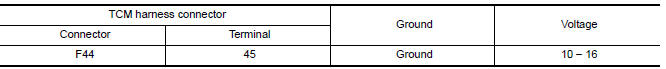
1.CHECK TCM POWER CIRCUIT 1
- Turn the ignition switch OFF.
- Disconnect the TCM connector.
- Check the voltage between the TCM harness connector terminals and
ground.
Is the inspection result normal?
YES >> GO TO 2.
NO >> GO TO 4.
2.CHECK TCM POWER CIRCUIT 2
Check the voltage between the TCM harness connector terminals and ground. 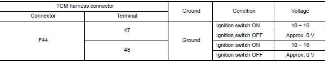
Is the inspection result normal?
YES >> GO TO 3.
NO >> GO TO 5.
3.CHECK TCM GROUND CIRCUIT
Check the continuity between TCM harness connector terminals and ground. 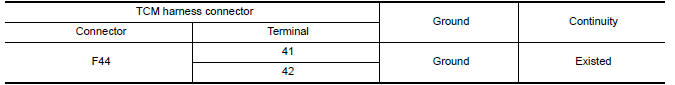
Is the inspection result normal?
YES >> Check intermittent incident. Refer to GI, "Intermittent Incident".
NO >> Repair or replace the malfunctioning parts.
4.DETECT MALFUNCTION ITEMS (PART 1)
Check the following items:
- Open or short circuit of the harness between battery positive terminal and TCM connectors terminal 45.
- 10A fuse [No.25, fuse block (J/B)]. Refer to PG "Terminal Arrangement".
Is the inspection result normal?
YES >> Check intermittent incident. Refer to GI, "Intermittent Incident".
NO >> Repair or replace the malfunctioning parts.
5.DETECT MALFUNCTION ITEMS (PART 2)
Check the following items:
- Open or short circuit of the harness between IPDM E/R harness connector terminal 21 and TCM connector terminals 47, 48.
- Harness open circuit or short circuit between the ignition switch and IPDM E/R. Refer to PG, "Wiring Diagram - Ignition Power Supply -".
- 10A fuse [No.49, IPDM E/R]. Refer to PG-62, "IPDM E/R Terminal Arrangement".
- IPDM E/R
Is the inspection result normal?
YES >> Check intermittent incident. Refer to GI, "Intermittent Incident".
NO >> Repair or replace the malfunctioning parts.
 P2760 Torque converter
Description This DTC is detected when the torque converter clutch solenoid valve is electrically normal but the torque converter clutch does not engage. This is not due to an electrical malfuncti ...

Other materials:
NISSAN Voice Recognition System (if so equipped)
The NISSAN Voice Recognition system allows
hands-free operation of the systems equipped on
this vehicle, such as the phone and navigation
systems.
To operate NISSAN Voice Recognition, press
the button located on the steering
wheel.
When prompted, speak the command for the
system you wi ...
Instrument lower panel LH
Removal and Installation
REMOVAL
Remove data link connector from instrument lower panel LH.
Remove hood and fuel filler handle assembly bolts (A) and position
hood and fuel filler handle assembly aside.
Remove instrument lower panel LH. Refer to IP "Exploded View".
a. Rel ...
Categories
- Manuals Home
- Nissan Versa Owners Manual
- Nissan Versa Service Manual
- Video Guides
- Questions & Answers
- External Resources
- Latest Updates
- Most Popular
- Sitemap
- Search the site
- Privacy Policy
- Contact Us

0.0061