Nissan Versa (N17): Microphone
Removal and Installation
REMOVAL
1. Remove the microphone (1) from the headlining using a suitable tool.
 Clip
Clip
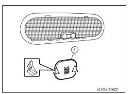
2. Disconnect the harness connector from microphone and remove.
INSTALLATION
Installation is in the reverse order of removal.
ANTENNA FEEDER
Feeder Layout
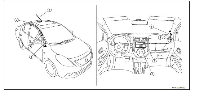
1. Antenna mast 2. Antenna feed 3. Clip 4. Harness connector 5. Audio unit 6. Harness connector
 Bluetooth antenna
Removal and Installation REMOVAL 1. Remove the rear seat cushion assembly. Refer to SE "Removal and Installation - Seat Cushion Assembly". 2. Remove the rear step plate (RH). 3. Remov ...
Roof antenna
Exploded View 1. Antenna mast 2. Antenna base Removal and Installation REMOVAL 1. Remove the headlining. Refer to INT "Removal and Installation". 2. Disconnect the antenna cable. ...
Other materials:
Additional service when replacing
TCM
Description
Always perform the following items when the TCM is replaced.
LOADING OF THE CALIBRATION DATA
The TCM acquires calibration data (individual characteristic value) of
each solenoid that is stored in the
ROM assembly (in the control valve). This enables the TCM to perform
accur ...
P0713 Transmission fluid temperature
sensor A
DTC Logic
DTC DETECTION LOGIC
DTC
Trouble diagnosis name
DTC detection condition
Possible causes
P0713
Transmission Fluid Temperature
Sensor "A" Circuit High
Under the following diagnosis
conditions, the A/T fluid temperature
identified by TCM is −
...
Categories
- Manuals Home
- Nissan Versa Owners Manual
- Nissan Versa Service Manual
- Video Guides
- Questions & Answers
- External Resources
- Latest Updates
- Most Popular
- Sitemap
- Search the site
- Privacy Policy
- Contact Us

0.0055