Nissan Versa (N17): Oil pump
Exploded View
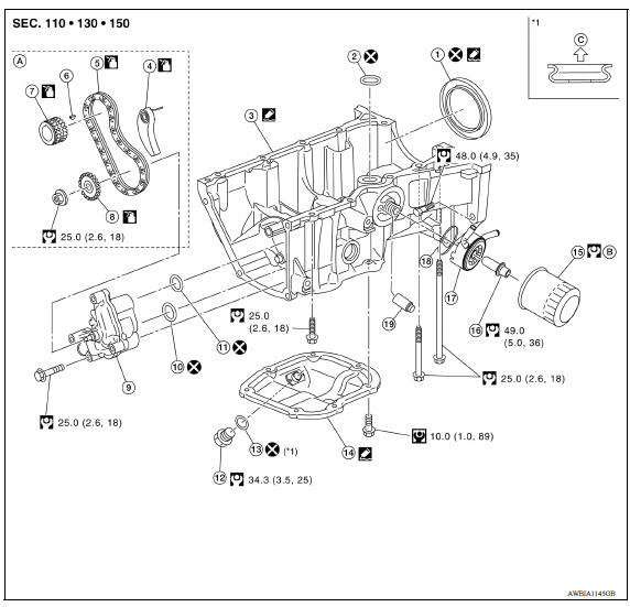
1. Rear oil seal 2. Oring 3. Oil pan (upper) 4. Oil pump chain tensioner (for oil pump drive chain) 5. Oil pump drive chain 6. Crankshaft key 7. Crankshaft sprocket 8. Oil pump sprocket 9. Oil pump 10. Oring 11. Oring 12. Oil pan drain plug 13. Drain plug washer 14. Oil pan (lower) 15. Oil filter 16. Connector bolt 17. Oil cooler 18. Oring 19. Relief valve
Removal and Installation
REMOVAL
- Drain engine oil.
- Remove timing chain and oil pump drive chain.
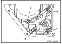
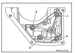
- Loosen the oil pump bolts in the reverse order as shown.
- Remove oil pump and Orings.
CAUTION:
- Do not reuse Orings.
- Do not disassemble oil pump.
INSTALLATION
- Install new Orings on the oil pan (upper) before installing the oil pump. CAUTION: Do not reuse Orings.
- Install the oil pump.
- Tighten the oil pump bolts to specification in the order shown.
- Install timing chain and oil pump drive chain.
INSPECTION AFTER INSTALLATION
- Before starting engine, check oil/fluid levels, including engine coolant and engine oil. If less than required quantity, fill to the specified level.
- Use procedure below to check for fuel leakage.
- Turn ignition switch ON (with engine stopped). With fuel pressure applied to fuel piping, check for fuel leakage at connection points.
- Start engine. With engine speed increased, check again for fuel leakage at connection points.
- Run engine to check for unusual noise and vibration.
NOTE:
If hydraulic pressure inside timing chain tensioner drops after removal and installation, slack in the guide may generate a pounding noise during and just after engine start. However, this is normal. Noise will stop after hydraulic pressure rises.
- Warm up engine thoroughly to make sure there is no leakage of fuel, exhaust gas, or any oils/fluids including engine oil and engine coolant.
- Bleed air from passages in lines and hoses, such as in cooling system.
- After cooling down engine, again check oil/fluid levels, including engine oil and engine coolant. Refill to specified level, if necessary.
- Summary of the inspection items:
| Item | Before starting engine | Engine running | After engine stopped | |
| Engine coolant | Level | Leakage | Level | |
| Engine oil | Level | Leakage | Level | |
| Transmission/ transaxle fluid | A/T and CVT Models | Leakage | Level/Leakage | Leakage |
| M/T Models | Level/Leakage | Leakage | Level/Leakage | |
| Other oils and fluids* | Level | Leakage | Level | |
| Fuel | Leakage | Leakage | Leakage | |
| Exhaust gas | Leakage | |||
*Power steering fluid, brake fluid, etc.
 Oil filter
Removal and Installation REMOVAL Remove engine under cover. Drain engine oil. Remove oil filter using Tool (A). : Front Tool number : KV10115801 (J38956) WARNING: Be careful ...
Oil cooler
Exploded View 1. Radiator hose (upper) 2. Hose clamp 3. Radiator hose (lower) 4. Hose clamp 5. Water hose 6. Oil cooler 7. Connector bolt 8. Water hose 9. Oring A. To radiator (upper side) B. T ...
Other materials:
Bluetooth Hands-Free Phone System without Navigation System (Type A) (if so
equipped)
WARNING
Use a phone after stopping your vehicle
in a safe location. If you have to use a
phone while driving, exercise extreme
caution at all times so full attention may
be given to vehicle operation.
If you are unable to devote full attention
to vehicle operation while talking on
...
Compression pressure
Inspection
Warm up engine and then turn it off.
Release fuel pressure.
Remove ignition coil and spark plug from each cylinder.
Connect engine tachometer (not required in use of CONSULT).
Install compression gauge (B) with an adapter (A) (commercial
service tool) onto spark plug hole.
...
Categories
- Manuals Home
- Nissan Versa Owners Manual
- Nissan Versa Service Manual
- Video Guides
- Questions & Answers
- External Resources
- Latest Updates
- Most Popular
- Sitemap
- Search the site
- Privacy Policy
- Contact Us

0.0051