Nissan Versa (N17): P0340 CMP sensor (PHASE)
DTC Logic
DTC DETECTION LOGIC
NOTE: If DTC P0340 is displayed with DTC P0643, first perform the trouble diagnosis for DTC P0643. Refer to EC, "DTC Logic".
| DTC No. | Trouble diagnosis name | DTC detecting condition | Possible cause |
| P0340 | Camshaft position sensor (PHASE) circuit |
|
|
DTC CONFIRMATION PROCEDURE
1.PRECONDITIONING
If DTC Confirmation Procedure has been previously conducted, always perform the following procedure before conducting the next test.
- Turn ignition switch OFF and wait at least 10 seconds.
- Turn ignition switch ON.
- Turn ignition switch OFF and wait at least 10 seconds.
TESTING CONDITION:
Before performing the following procedure, confirm that battery voltage is more than 10.5 V with ignition switch ON.
>> GO TO 2.
2.PERFORM DTC CONFIRMATION PROCEDUREI
- Start engine and let it idle for at least 5 seconds.
If engine does not start, crank engine for at least 2 seconds.
- Check 1st trip DTC.
Is 1st trip DTC detected?
YES >> Go to EC, "Diagnosis Procedure".
NO >> GO TO 3.
3.PERFORM DTC CONFIRMATION PROCEDUREII
- Keep engine speed at more than 800 rpm for at least 5 seconds.
- Check 1st trip DTC.
Is 1st trip DTC detected?
YES >> Go to EC, "Diagnosis Procedure".
NO >> INSPECTION END
Diagnosis Procedure
1.CHECK STARTING SYSTEM
Turn ignition switch to START position.
Does the engine turn over? Does the starter motor operate?
YES >> GO TO 2.
NO >> Check starting system.
2.CHECK GROUND CONNECTION
- Turn ignition switch OFF.
- Check ground connection E15. Refer to Ground Inspection in GI, "Circuit Inspection".
Is the inspection result normal?
YES >> GO TO 3.
NO >> Repair or replace ground connection.
3.CHECK INTAKE CAMSHAFT POSITION SENSOR (PHASE) POWER SUPPLY CIRCUIT
- Disconnect intake camshaft position sensor (PHASE) harness connector.
- Turn ignition switch ON.
- Check the voltage between intake camshaft position sensor (PHASE)
harness connector and ground.
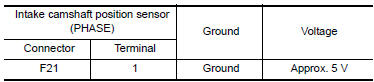
Is the inspection result normal?
YES >> GO TO 4.
NO >> Repair open circuit or short to ground or short to power in harness or connectors.
4.CHECK INTAKE CAMSHAFT POSITION SENSOR GROUND CIRCUIT FOR OPEN AND SHORT
- Turn ignition switch OFF.
- Disconnect ECM harness connectors.
- Check the continuity between intake camshaft position sensor (PHASE)
harness connector and ECM harness
connector.
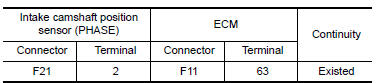
4. Also check harness for short to ground and short to power.
Is the inspection result normal?
YES >> GO TO 5.
NO >> Repair open circuit or short to ground or short to power in harness or connectors.
5.CHECK INTAKE CAMSHAFT POSITION SENSOR (PHASE) INPUT SIGNAL CIRCUIT FOR OPEN AND SHORT
1. Check the continuity between intake
camshaft position sensor (PHASE) harness connector and ECM harness
connector. 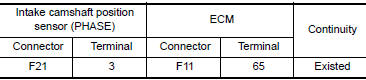
2. Also check harness for short to ground and short to power.
Is the inspection result normal?
YES >> GO TO 6.
NO >> Repair open circuit or short to ground or short to power in harness or connectors.
6.CHECK INTAKE CAMSHAFT POSITION SENSOR (PHASE)
Refer to EC, "Component Inspection".
Is the inspection result normal?
YES >> GO TO 7.
NO >> Replace intake camshaft position sensor (PHASE). Refer to EM, "Exploded View".
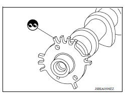
7.CHECK CAMSHAFT (INT)
Check the following.
- Accumulation of debris to the signal plate of camshaft rear end
- Chipping signal plate of camshaft rear end
Is the inspection result normal?
YES >> GO TO 8.
NO >> Remove debris and clean the signal plate of camshaft rear end or replace camshaft. Refer to EM, "Removal and Installation".
8.CHECK INTERMITTENT INCIDENT
Refer to GI, "Intermittent Incident".
>> INSPECTION END
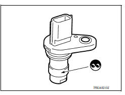
Component Inspection
1.CHECK INTAKE CAMSHAFT POSITION SENSORI
- Turn ignition switch OFF.
- Loosen the fixing bolt of the sensor.
- Disconnect intake camshaft position sensor harness connector.
- Remove the sensor. Refer to EM, "Exploded View".
- Visually check the sensor for chipping.
Is the inspection result normal?
YES >> GO TO 2.
NO >> Replace intake camshaft position sensor. Refer to EM, "Exploded View".
2.CHECK INTAKE CAMSHAFT POSITION SENSORII
Check resistance intake camshaft position sensor terminals as follows.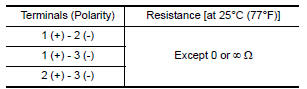
Is the inspection result normal?
YES >> INSPECTION END
NO >> Replace intake camshaft position sensor. Refer to EM, "Exploded View".
 P0335 CKP sensor (POC)
Other materials:
Precautions when starting and driving
WARNING
Do not leave children or adults who
would normally require the assistance
of others alone in your vehicle. Pets
should also not be left alone. They
could accidentally injure themselves or
others through inadvertent operation of
the vehicle. Also, on hot, sunny days,
tempera ...
General maintenance
During the normal day-to-day operation of the
vehicle, general maintenance should be performed
regularly as prescribed in this section. If
you detect any unusual sounds, vibrations or
smells, be sure to check for the cause or have a
NISSAN dealer do it promptly. In addition, it is
recommended ...
Categories
- Manuals Home
- Nissan Versa Owners Manual
- Nissan Versa Service Manual
- Video Guides
- Questions & Answers
- External Resources
- Latest Updates
- Most Popular
- Sitemap
- Search the site
- Privacy Policy
- Contact Us

0.0065