Nissan Versa (N17): P0705 Transmission range sensor A
DTC Logic
DTC DETECTION LOGIC
| DTC | Trouble diagnosis name | DTC detection condition | Possible causes |
|
P0705 |
Transmission Range Sensor A Circuit (PRNDL Input) | Two or more range signals simultaneously
stay ON continuously for 5 seconds under the
following diagnosis condition 1 and 2: - Diagnosis condition 1 (continued for 5 seconds or more) - TCM power supply voltage: More than 11 V - Diagnosis condition 2 (continued for 2 seconds or more) - Vehicle speed: Less than 3 km/h (2 MPH) - Accelerator pedal position: 0.6/8 or less - Idle switch: ON - Stop lamp switch: ON |
|
DTC CONFIRMATION PROCEDURE
CAUTION: Be careful of the driving speed.
1.PREPARATION BEFORE WORK
If another "DTC CONFIRMATION PROCEDURE" occurs just before, turn ignition switch OFF and wait for at least 10 seconds, then perform the next test.
>> GO TO 2.
2.CHECK DTC DETECTION
- Start the engine.
- Maintain the following conditions.
- Shift the selector lever through entire positions from "P" to "L". (Hold the selector lever at each position for 10 seconds or more.)
- Check the first trip DTC.
Is "P0705" detected?
YES >> Go to TM "Diagnosis Procedure".
NO >> INSPECTION END
Diagnosis Procedure
1.CHECK TCM INPUT SIGNALS
With CONSULT
- Turn ignition switch ON.
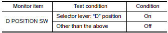
- Select "Data Monitor" in "TRANSMISSION".
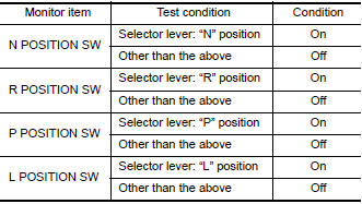
- Select "D POSITION SW", "N POSITION SW", "R POSITION SW", "P POSITION SW" and "L POSITION SW".
- Shift the selector lever through entire positions from "P" to "L" and
check ON/OFF of each monitor item.
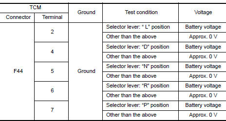
Without CONSULT
- Turn ignition switch OFF.
- Disconnect TCM connector.
- Turn ignition switch ON.
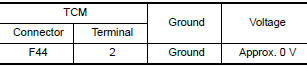
- Shift the selector lever from "P" to "L" and check voltage between TCM
harness connector terminals and
ground.
Is the inspection result normal?
YES >> Check intermittent incident. Refer to GI "Intermittent Incident".
NO-1 ["D POSITION SW" is "ON" when selector is not in "D" position. (Or connector terminal 4 is at power voltage.)]>>GO TO 2.
NO-2 ["N POSITION SW" is "ON" when selector is not in "N" position. (Or connector terminal 5 is at power voltage.)]>>GO TO 4.
NO-3 ["R POSITION SW" is "ON" when selector is not in "R" position. (Or connector terminal 6 is at power voltage.)]>>GO TO 6.
NO-4 ["P POSITION SW" is "ON" when selector is not in "P" position. (Or connector terminal 7 is at power voltage.)]>>GO TO 8.
NO-5 ["L POSITION SW" is "ON" when selector is not in "L" position. (Or connector terminal 2 is at power voltage.)]>>GO TO 10.
2.CHECK D POSITION SW CIRCUIT (PART 1)
- Turn ignition switch OFF.
- Disconnect TCM connector.
- Check continuity between TCM harness connector terminals.
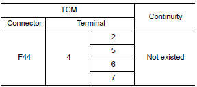
Is the inspection result normal?
YES >> GO TO 3.
NO >> Repair or replace malfunctioning parts.
3.CHECK D POSITION SW CIRCUIT (PART 2)
- Disconnect transmission position switch connector.
- Turn ignition switch ON.
- Check voltage between TCM harness connector terminal and ground.
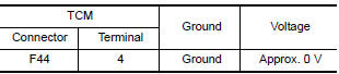
Is the inspection result normal?
YES >> GO TO 12.
NO >> Repair or replace malfunctioning parts.
4.CHECK N POSITION SW CIRCUIT (PART 1)
- Turn ignition switch OFF.
- Disconnect TCM connector.
- Check continuity between TCM harness connector terminals.
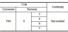
Is the inspection result normal?
YES >> GO TO 5.
NO >> Repair or replace malfunctioning parts.
5.CHECK N POSITION SW CIRCUIT (PART 2)
- Disconnect transmission position switch connector.
- Turn ignition switch ON.
- Check voltage between TCM harness connector terminal and ground.
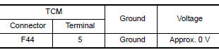
Is the inspection result normal?
YES >> GO TO 12.
NO >> Repair or replace malfunctioning parts.
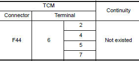
6.CHECK P POSITION SW CIRCUIT (PART 1)
- Turn ignition switch OFF.
- Disconnect TCM connector.
- Check continuity between TCM harness connector terminals.
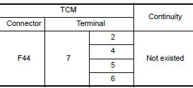
Is the inspection result normal?
YES >> GO TO 7.
NO >> Repair or replace malfunctioning parts.
7.CHECK P POSITION SW CIRCUIT (PART 2)
- Disconnect transmission position switch connector.
- Turn ignition switch ON.
- Check voltage between TCM harness connector terminal and ground.
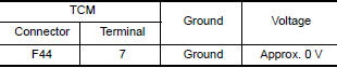
Is the inspection result normal?
YES >> GO TO 12.
NO >> Repair or replace malfunctioning parts.
8.CHECK R POSITION SW CIRCUIT (PART1)
- Turn ignition switch OFF.
- Disconnect TCM connector.
- Check continuity between TCM harness connector terminals.
Is the inspection result normal?
YES >> GO TO 9.
NO >> Repair or replace malfunctioning parts.
9.CHECK R POSITION SW CIRCUIT (PART 2)
- Disconnect transmission position switch connector.
- Turn ignition switch ON.
- Check voltage between TCM harness connector terminal and ground.
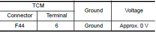
Is the inspection result normal?
YES >> GO TO 12.
NO >> Repair or replace malfunctioning parts.
10.CHECK L POSITION SWITCH CIRCUIT (PART 1)
- Turn ignition switch OFF.
- Disconnect TCM connector.
- Check continuity between TCM harness connector terminals.
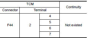
Is the inspection result normal?
YES >> GO TO 11.
NO >> Repair or replace malfunctioning parts.
11.CHECK L POSITION SWITCH CIRCUIT (PART 2)
- Disconnect transmission position switch connector.
- Turn ignition switch ON.
- Check voltage between TCM harness connector terminal and ground.
Is the inspection result normal?
YES >> GO TO 12.
NO >> Repair or replace malfunctioning parts.
12.CHECK TRANSMISSION RANGE SWITCH
Check transmission range switch. Refer to TM "Component Inspection (Transmission Range Switch)".
Is the check result normal?
YES >> Check intermittent incident. Refer to GI "Intermittent Incident".
NO >> Repair or replace malfunctioning parts.
Component Inspection (Transmission Range Switch)
1.CHECK TRANSMISSION RANGE SWITCH
Check continuity between transmission range switch connector terminals.
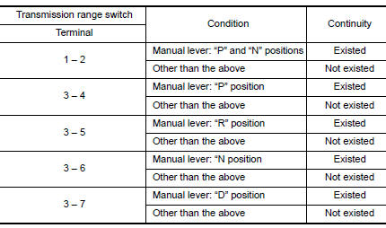
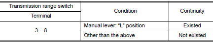
Is the inspection result normal?
YES >> INSPECTION END
NO >> There is a malfunction of transmission range switch. Replace transaxle assembly. Refer to TM "Removal and Installation".
 P062F EEPROM
Description TCM compares the calculated value stored in the flash ROM with the value stored in TCM. If the calculated value does not agree with the stored value, TCM judges this as a malfunction. ...

Other materials:
Bluetooth Hands-Free Phone System without Navigation System (Type A) (if so
equipped)
WARNING
Use a phone after stopping your vehicle
in a safe location. If you have to use a
phone while driving, exercise extreme
caution at all times so full attention may
be given to vehicle operation.
If you are unable to devote full attention
to vehicle operation while talking on
...
P0706 Transmission range sensor A
DTC Logic
DTC DETECTION LOGIC
DTC
Trouble diagnosis name
DTC detection condition
Possible causes
P0706
Transmission Range Sensor
"A" Circuit Range/Performance
The following diagnosis conditions
are met and the position
signal is OFF continuously for
15 ...
Categories
- Manuals Home
- Nissan Versa Owners Manual
- Nissan Versa Service Manual
- Video Guides
- Questions & Answers
- External Resources
- Latest Updates
- Most Popular
- Sitemap
- Search the site
- Privacy Policy
- Contact Us

0.0054