Nissan Versa (N17): P0705 Transmission range switch A
DTC Logic
DTC DETECTION LOGIC
| DTC | Trouble diagnosis name | DTC detection condition | Possible causes |
| P0705 | Transmission Range Sensor "A" Circuit Malfunction (PRNDL input) | The following diagnosis conditions
are met and 2 or more position
signals are ON at the
same time for 5 seconds or
more. - Diagnosis condition - TCM power supply voltage: 10 V <TCM power supply voltage <16 V |
|
DTC CONFIRMATION PROCEDURE
1.PREPARATION BEFORE WORK
If another "DTC CONFIRMATION PROCEDURE" occurs just before, turn the ignition switch OFF and wait for at least 10 seconds, then perform the next test.
>> GO TO 2.
2.CHECK DTC DETECTION
- Turn ignition switch ON.
- Shift the selector lever to the entire position from P to 1. (Hold the selector lever at each position for 10 seconds or more.)
- Check the first trip DTC.
Is "P0705" detected?
YES >> Go to TM, "Diagnosis Procedure".
NO >> INSPECTION END
Diagnosis Procedure
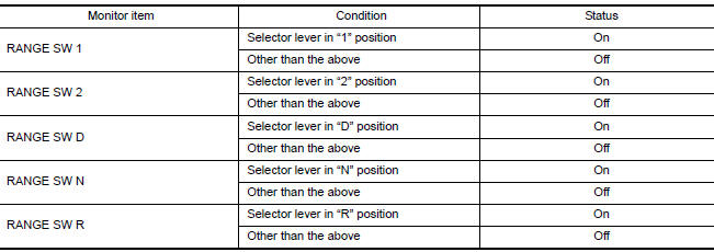
1.CHECK TCM INPUT SIGNALS
With CONSULT
- Turn ignition switch ON.
- Select "TRANSMISSION" "DATA MONITOR".
- Select the "D position switch", "N position switch", "R position switch", "P position switch", "2 position switch", and "1 position switch".
- Shift the selector lever to the entire position from P to 1, and check
the ON/OFF operation of each monitor
item.

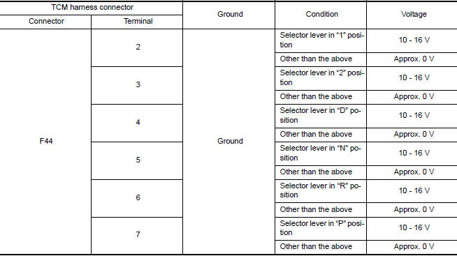
Without CONSULT.
- Turn ignition switch OFF.
- Disconnect the TCM connector.
- Turn ignition switch ON.
- Shift the selector lever to the entire position from P to 1, and check
the voltage between the TCM harness
connector terminal and ground.
Is the check result normal?
YES >> Check intermittent incident. Refer to GI, "Intermittent Incident".
NO-1 [D position SW is "On" when selector is not in D position. (Or, connector terminal 4 is at 10 - 16 V.)]>> GO TO 2.
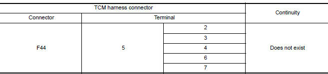
NO-2 [N position SW is "On" when selector is not in N position. (Or, connector terminal 5 is at 10 - 16 V.)]>> GO TO 4.
NO-3 [R position SW is "On" when selector is not in R position. (Or, connector terminal 6 is at 10 - 16 V.)]>> GO TO 6.
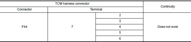
NO-4 [P position SW is "On" when selector is not in P position. (Or, connector terminal 7 is at 10 - 16 V.)]>> GO TO 8.
NO-5 [2 position SW is "On" when selector is not in 2 position. (Or, connector terminal 3 is at 10 - 16 V.)]>> GO TO 10.
NO-6 [1 position SW is "On" when selector is not in 1 position. (Or, connector terminal 2 is at 10 - 16 V.)]>> GO TO 12.
2.CHECK D POSITION SW CIRCUIT (CHECK 1)
- Turn ignition switch OFF.
- Disconnect the TCM connector.
- Check the continuity between the TCM harness connector terminals.
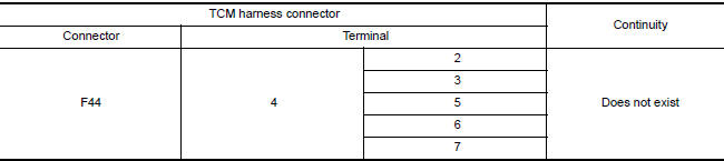
Is the check result normal?
YES >> GO TO 3.
NO >> Repair or replace the malfunctioning parts.
3.CHECK D POSITION SW CIRCUIT (CHECK 2)
- Disconnect the transmission range switch connector.
- Turn the ignition switch ON.
- Check the voltage between the TCM harness connector and ground.
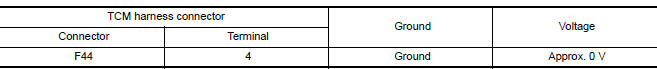
Is the check result normal?
YES >> GO TO 14.
NO >> Repair or replace the malfunctioning parts.
4.CHECK N POSITION SW CIRCUIT (CHECK 1)
- Turn ignition switch OFF.
- Disconnect the TCM connector.
- Check the continuity between the TCM harness connector terminals.
Is the check result normal?
YES >> GO TO 5.
NO >> Repair or replace the malfunctioning parts.
5.CHECK N POSITION SW CIRCUIT (CHECK 2)
- Disconnect the transmission range switch connector.
- Turn ignition switch ON.
- Check the voltage between the TCM harness connector and ground.

Is the check result normal?
YES >> GO TO 14.
NO >> Repair or replace the malfunctioning parts.
- 6.CHECK P POSITION SW CIRCUIT (CHECK 1)
- Turn ignition switch OFF.
- Disconnect the TCM connector.
- Check the continuity between the TCM harness connector terminals.
Is the check result normal?
YES >> GO TO 7.
NO >> Repair or replace the malfunctioning parts.
7.CHECK P POSITION SW CIRCUIT (CHECK 2)
- Disconnect the transmission range switch connector.
- Turn ignition switch ON.
- Check the voltage between the TCM harness connector and ground.

Is the check result normal?
YES >> GO TO 14.
NO >> Repair or replace the malfunctioning parts.
8.CHECK R POSITION SW CIRCUIT (CHECK 1)
- Turn ignition switch OFF.
- Disconnect the TCM connector.
- Check the continuity between the TCM harness connector terminals.
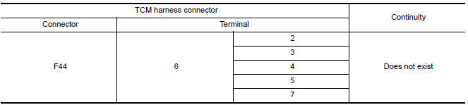
Is the check result normal?
YES >> GO TO 9.
NO >> Repair or replace the malfunctioning parts.
9.CHECK R POSITION SW CIRCUIT (CHECK 2)
- Disconnect the transmission range switch connector.
- Turn ignition switch ON.
- Check the voltage between the TCM harness connector and ground.
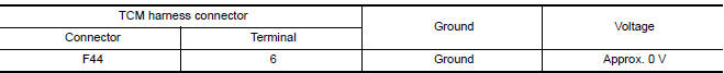
Is the check result normal?
YES >> GO TO 14.
NO >> Repair or replace the malfunctioning parts.
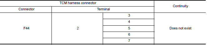
10.CHECK 2 POSITION SW CIRCUIT (CHECK 1)
- Turn ignition switch OFF.
- Disconnect the TCM connector.
- Check the continuity between the TCM harness connector terminals.
Is the check result normal?
YES >> GO TO 11.
NO >> Repair or replace the malfunctioning parts.
11.CHECK 2 POSITION SW CIRCUIT (CHECK 2)
- Disconnect the transmission range switch connector.
- Turn ignition switch ON.
- Check the voltage between the TCM harness connector and ground.

Is the check result normal?
YES >> GO TO 14.
NO >> Repair or replace the malfunctioning parts.
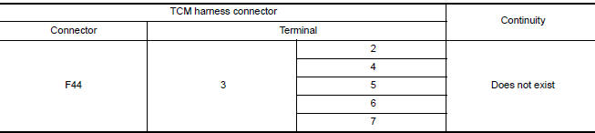
12.CHECK 1 POSITION SW CIRCUIT (CHECK 1)
- Turn ignition switch OFF.
- Disconnect the TCM connector.
- Check the continuity between the TCM harness connector terminals.
Is the check result normal?
YES >> GO TO 13.
NO >> Repair or replace the malfunctioning parts.
13.CHECK 1 POSITION SW CIRCUIT (CHECK 2)
- Disconnect the transmission range switch connector.
- Turn ignition switch ON.
- Check the voltage between the TCM harness connector and ground.

Is the check result normal?
YES >> GO TO 14.
NO >> Repair or replace the malfunctioning parts.
14.CHECK TRANSMISSION RANGE SWITCH
Check the transmission range switch. Refer to TM, "Component Inspection (Transmission Range Switch)".
Is the check result normal?
YES >> Check intermittent incident. Refer to GI, "Intermittent Incident".
NO >> Repair or replace the malfunctioning parts.
Component Inspection (Transmission Range Switch)
1.CHECK TRANSMISSION RANGE SWITCH
Check the continuity between the transmission range switch connector
terminals. 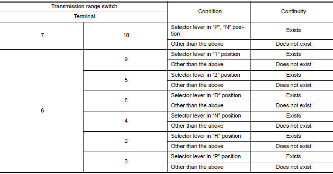
Is the check result normal?
YES >> INSPECTION END
NO >> There is a malfunction of the transmission range switch. Replace the transaxle assembly. Refer to TM, "Removal and Installation".
 P062F EEPROM
Description TCM checks the value read in FLASH ROM at ignition switch ON, and judges if there is writing failure to FLASH ROM or malfunction of FLASH ROM. DTC Logic DTC DETECTION LOGIC ...
P0706 Transmission range sensor A
DTC Logic DTC DETECTION LOGIC DTC Trouble diagnosis name DTC detection condition Possible causes P0706 Transmission Range Sensor "A" Circuit Range/Performance The ...
Other materials:
Steering wheel
Tilt operation
Push the lock lever 1 down and adjust the
steering wheel up or down 2 to the desired
position.
Pull the lock lever 1 up to lock the steering
wheel in place.
WARNING
Do not adjust the steering wheel while
driving. You could lose control of your
vehicle and cause an accid ...
Uniform tire quality grading
DOT (Department of Transportation) Quality
Grades: All passenger car tires must conform to
federal safety requirements in addition to these
grades.
Quality grades can be found where applicable on
the tire sidewall between tread shoulder and
maximum section width. For example:
Treadwear 200 ...
Categories
- Manuals Home
- Nissan Versa Owners Manual
- Nissan Versa Service Manual
- Video Guides
- Questions & Answers
- External Resources
- Latest Updates
- Most Popular
- Sitemap
- Search the site
- Privacy Policy
- Contact Us

0.0062