Nissan Versa (N17): P0848 Transmission fluid pressure SEN/SW B
DTC Logic
DTC DETECTION LOGIC
| DTC | Trouble diagnosis name | DTC detection condition | Possible causes |
| P0848 | Transmission Fluid Pressure Sensor/Switch B Circuit Low | The secondary pressure sensor voltage is 4.7
V or more continuously for 5 seconds or more
under the following diagnosis conditions: - Diagnosis conditions - CVT fluid temperature: −20C (−4F) or more - Secondary pressure target value: 5.7 MPa or less - TCM power supply voltage: More than 11 V |
- Harness or connector
(Secondary pressure sensor circuit is
shorted to power supply) - Secondary pressure sensor - Control valve assembly |
DTC CONFIRMATION PROCEDURE
1.PREPARATION BEFORE WORK
If another "DTC CONFIRMATION PROCEDURE" occurs just before, the ignition switch OFF and wait for at least 10 seconds, then perform the next test.
>> GO TO 2.
2.CHECK DTC DETECTION
With CONSULT
- Start the engine.
- Select "Data Monitor" in "TRANSMISSION".
- Select "FLUID TEMP".
- Maintain the following conditions for 10 seconds or more.
- Check the first trip DTC.
FLUID TEMP : −19C (−2.2F) or more
With GST
- Start the engine and wait for at least 10 seconds.
CAUTION: When the ambient temperature is −20C (−4F) or less and the engine is cold, warm up the engine for approximately 5 minutes.
- Check the first trip DTC.
Is "P0848"detected?
YES >> Go to TM "Diagnosis Procedure".
NO >> INSPECTION END
Diagnosis Procedure
1.CHECK SECONDARY PRESSURE SENSOR POWER SUPPLY CIRCUIT
- Turn ignition switch OFF.
- Disconnect CVT unit connector.
- Turn ignition switch ON.
- Check voltage between CVT unit harness connector terminal and ground.
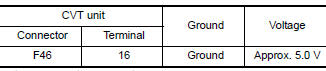
Is the inspection result normal?
YES >> GO TO 2.
NO >> Repair or replace malfunctioning parts.
2.CHECK SECONDARY PRESSURE SENSOR SIGNAL CIRCUIT
- Turn ignition switch OFF.
- Disconnect TCM connector.
- Check continuity between TCM harness connector terminals.
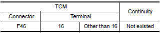
Is the inspection result normal?
YES >> GO TO 3.
NO >> Repair or replace malfunctioning parts.
3.CHECK TCM INPUT SIGNALS
- Connect all connectors removed.
- Start the engine.
- Check voltage between TCM harness connector terminal and ground.
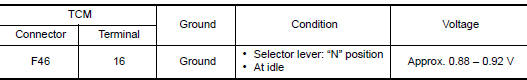
Is the inspection result normal?
YES >> Check intermittent incident. Refer to GI "Intermittent Incident".
NO >> There is a malfunction of secondary pressure sensor. Replace transaxle assembly. Refer to TM "Removal and Installation".
 P0847 Transmission fluid pressure
SEN/SW B
P0847 Transmission fluid pressure
SEN/SW BP0863 TCM Communication
DTC Logic DTC DETECTION LOGIC DTC Trouble diagnosis name DTC detection condition Possible causes P0863 TCM Communication Circui An error is detected at the initial CA ...
Other materials:
Spark plug
Exploded View
1. Ignition coil 2. Spark plug
Removal and Installation
REMOVAL
1. Remove ignition coil.
CAUTION:
Do not drop or shock ignition coil.
2. Remove spark plug using a suitable tool.
Diameter (a) : 14 mm (0.55 in)
CAUTION:
Do not drop or shock spark plug.
INSPECTION AFTER REM ...
Camshaft
Exploded View
1. Camshaft bracket (No. 2 to 5) 2. Camshaft bracket (No. 1) 3. Camshaft
sprocket (EXH)
4. Exhaust valve timing control solenoid
valve 5. Oring 6. Camshaft sprocket (INT)
7. Plug (EXH) 8. Washer (EXH) 9. Oil filter (for exhaust valve timing control
solenoid valve)
10. Cylinde ...
Categories
- Manuals Home
- Nissan Versa Owners Manual
- Nissan Versa Service Manual
- Video Guides
- Questions & Answers
- External Resources
- Latest Updates
- Most Popular
- Sitemap
- Search the site
- Privacy Policy
- Contact Us

0.0064